- Back door courtesy switch signal
- Vehicle information signal
Lexus NX: System Diagram
Lexus NX Service Manual / Audio & Visual & Telematics / Park Assist / Monitoring / Parking Assist Monitor System / System Diagram
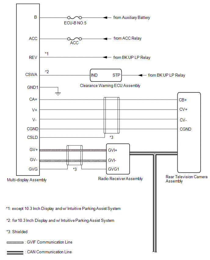
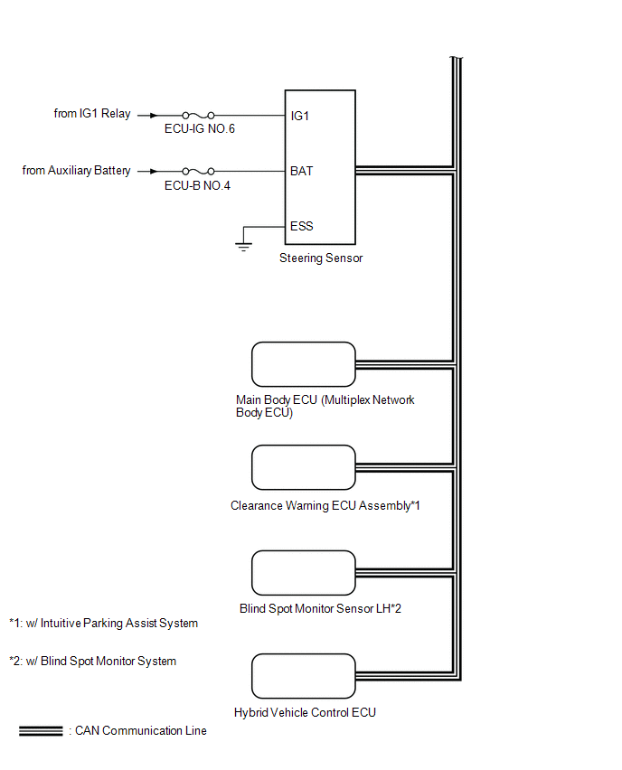
SYSTEM DIAGRAM
 Communication Table
 | Sender | Receiver | Signal | Line |
|---|---|---|---|
| Radio Receiver Assembly | Multi-display assembly | Camera information signal | GVIF Cable |
| Radio Receiver Assembly | Rear Television Camera Assembly | Camera information signal | CAN Communication Line |
| Steering Sensor | Rear Television Camera Assembly | Steering angle signal | CAN Communication Line |
| Hybrid Vehicle Control ECU | Rear Television Camera Assembly | Vehicle information signal | CAN Communication Line |
| Main Body ECU (Multiplex Network Body ECU) | Rear Television Camera Assembly | | CAN Communication Line |
| Clearance Warning ECU Assembly*1 | Rear Television Camera Assembly | Sonar information signal | CAN Communication Line |
| Blind Spot Monitor Sensor LH*2 | Rear Television Camera Assembly | RCTA operation condition signal | CAN Communication Line |
- *1: w/ Intuitive Parking Assist System
- *2: w/ Blind Spot Monitor System
READ NEXT:
 System Description
SYSTEM DESCRIPTION GENERAL (a) This system has a rear television camera assembly mounted on the back door to display an image of the area behind the vehicle on the display. The display panel also show
How To Proceed With Troubleshooting
CAUTION / NOTICE / HINT HINT:
Use the following procedure to troubleshoot the parking assist monitor system.
*: Use the Techstream.
PROCEDURE 1. VEHICLE BROUGHT TO WORKSHOP
NEXT
Initialization
INITIALIZATION INITIALIZE PARKING ASSIST MONITOR SYSTEM (a) When the "!" mark is displayed on the multi-display assembly, correct the steering angle neutral point using the following method. (1) Fully
SEE MORE:
Components
COMPONENTS ILLUSTRATION *A w/o AVS *B w/ AVS *1 REAR SPEED SENSOR LH *2 REAR SUSPENSION ARM COVER LH *3 REAR UPPER CONTROL ARM ASSEMBLY LH *4 PARKING BRAKE WIRE BRACKET N*m (kgf*cm, ft.*lbf): Specified torque * For use with ball joint lock nut wrench
On-vehicle Inspection
ON-VEHICLE INSPECTION PROCEDURE 1. INSPECT RADIO SETTING CONDENSER (a) With the radio setting condenser installed, check that there is no looseness or other abnormalities. (b) Measure the resistance of the radio setting condenser according to the value(s) in the table below. Standard Resistance:
© 2016-2026 Copyright www.lexunx.com
