Lexus NX: PIG Power Supply Voltage (C1552,C1554)
DESCRIPTION
When a problem occurs in the power steering system, the power source relay circuit is shut off to stop the power assist.
| DTC No. | Detection Item | DTC Detection Condition | Trouble Area | Warning Indicate | Return-to-normal Condition |
|---|---|---|---|---|---|
| C1552 | PIG Power Supply Voltage | PIG power source circuit malfunction inside ECU |
| On | After normal confirmation |
| C1554 | Power Supply Relay Failure | Power source relay circuit malfunction |
| On | Power switch on (IG) again |
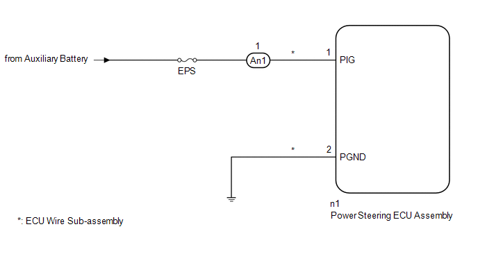
WIRING DIAGRAM
CAUTION / NOTICE / HINT
NOTICE:
If the power steering ECU assembly has been replaced, perform assist map writing.
Click here .gif)
HINT:
Inspect the fuses for circuits related to this system before performing the following procedure.
PROCEDURE
| 1. | CHECK CONNECTOR CONNECTION CONDITION AND GROUND WIRE |
(a) Check the connection condition of the ECU wire sub-assembly and power steering ECU assembly connectors.
OK:
The ECU wire sub-assembly and power steering ECU assembly connectors are securely connected.
(b) Check that the ground wire is securely installed with the bolt.
Click here
OK:
The ground wire is securely installed with the bolt.
| NG | .gif) | CONNECT CONNECTOR OR INSTALL GROUND WIRE |
|
.gif)
| 2. | READ VALUE USING TECHSTREAM (PIG POWER SUPPLY) |
(a) Turn the power switch off.
(b) Connect the Techstream to the DLC3.
(c) Turn the power switch on (IG).
(d) Turn the Techstream on.
(e) Enter the following menus: Chassis / EMPS / Data List.
(f) Select the item "PIG Power Supply" in the Data List and read the value displayed on the Techstream.
Chassis > EMPS > Data List| Tester Display | Measurement Item | Range | Normal Condition | Diagnostic Note |
|---|---|---|---|---|
| PIG Power Supply | Power source voltage to active motor | Min.: 0.0000 V Max.: 20.1531 V | Always: 9 to 16 V | - |
| Tester Display |
|---|
| PIG Power Supply |
OK:
The normal condition value is displayed on the Techstream.
| OK | | CHECK INTERMITTENT PROBLEMS |
|
| 3. | CHECK HARNESS AND CONNECTOR (AUXILIARY BATTERY - ECU WIRE SUB-ASSEMBLY) |
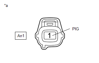
| (a) Disconnect the An1 ECU wire sub-assembly connector. |
|
(b) Measure the voltage according to the value(s) in the table below.
Standard Voltage:
| Tester Connection | Condition | Specified Condition |
|---|---|---|
| An1-1 (PIG) - Body ground | Always | 9 to 16 V |
| NG | | REPAIR OR REPLACE HARNESS OR CONNECTOR |
|
| 4. | CHECK ECU WIRE SUB-ASSEMBLY |
| (a) Connect the An1 connector to the ECU wire sub-assembly. |
|
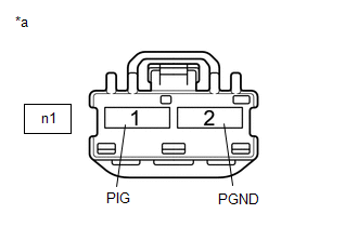
(b) Disconnect the n1 power steering ECU assembly connector.
(c) Measure the voltage according to the value(s) in the table below.
Standard Voltage:
| Tester Connection | Condition | Specified Condition |
|---|---|---|
| n1-1 (PIG) - Body ground | Always | 9 to 16 V |
(d) Measure the resistance according to the value(s) in the table below.
Standard Resistance:
| Tester Connection | Condition | Specified Condition |
|---|---|---|
| n1-2 (PGND) - Body ground | Always | Below 1 Ω |
| OK | | REPLACE POWER STEERING ECU ASSEMBLY |
| NG | | REPAIR OR REPLACE ECU WIRE SUB-ASSEMBLY |
READ NEXT:
 Error in Matching of ECUs (C1567)
DESCRIPTION Based on the ECM signal, the power steering ECU assembly determines if the correct type of ECM is installed. DTC No. Detection Item DTC Detection Condition Trouble Area Warning
Assist Map Number Un-Writing (C1581)
DESCRIPTION This DTC will be stored if the power steering ECU assembly determines that the assist map is not written in the ECU. DTC No. Detection Item DTC Detection Condition Trouble Area
Assist Map Number Mismatch (C1582)
DESCRIPTION When an incorrect hybrid vehicle control ECU, an incorrect Skid control ECU or an incorrect main body ECU is installed after the assist map has been written in the power steering ECU assem
SEE MORE:
Diagnostic Trouble Code Chart
DIAGNOSTIC TROUBLE CODE CHART Power Back Door System DTC No. Detection Item Link B2205 Kick Sensor Circuit B2220 Back Door Motor Circuit B2226 PBD Unit Pulse Sensor LH Circuit B2227 PBD Unit Pulse Sensor RH Circuit B222A PBD Touch Sensor LH Ci
Inspection
INSPECTION PROCEDURE 1. INSPECT HEATER ACCESSORY ASSEMBLY *a Component without harness connected (Heater Accessory Assembly (Heater Water Pump)) (a) Check the motor operation. (1) Apply the positive (+) lead of the auxiliary battery to terminal 2 and the negative (-) lead to terminal 1. OK:
