- DTC judgment completed
- System normal
Lexus NX: Poor Engine Power (P3190,P3191)
Lexus NX Service Manual / Engine & Hybrid System / 2ar-fxe (engine Control) / Sfi System / Poor Engine Power (P3190,P3191)
DESCRIPTION
The ECM receives signals from the hybrid vehicle control ECU such as the requested engine torque, target engine speed and engine cranking status, and controls the engine output based on the target engine speed and requested torque.
| DTC No. | Detection Item | DTC Detection Condition | Trouble Area | MIL | Memory |
|---|---|---|---|---|---|
| P3190 | Poor Engine Power | When all of the following conditions are met (1 trip detection logic):
|
| Comes on | DTC stored |
| P3191 | Engine does not Start | When all of the following conditions are met (1 trip detection logic):
|
| Comes on | DTC stored |
MONITOR DESCRIPTION
- The ECM receives signals such as requested engine torque, target engine speed and engine cranking status from the hybrid vehicle control ECU.
- The ECM controls engine start and stop and throttle valve angle based on the signals received from the hybrid vehicle control ECU.
- The ECM receives the actual engine torque calculated by the hybrid vehicle control ECU based on the generator torque.
-
When the actual engine torque is less than 20% of the requested engine torque*, the ECM judges that the engine output is abnormal and stores DTC P3190.
(The engine may not have started in the above situation.)
- *: Requested torque = Requested Engine Torque (kW) / HV Target Engine Speed (rpm) x 9549
-
If the ECM does not detect engine start torque (actual engine torque) even though it has received an engine start request and started the engine, it stores DTC P3191.
HINT:
-
When DTCs P3190, P3191 and P3193 are output, the engine may be stopped due to the engine condition.
At this time, after adding fuel or performing repairs, clear the DTCs. Then turn the power switch off to return to the normal condition.
- When this DTC is output and the engine is stopped, the HV battery cannot be charged since the vehicle is driven with the motor only. If the vehicle continues to be driven under this condition, the HV battery becomes depleted ultimately and the power switch cannot be turned on (READY).
-
When DTC P3190 or P3191 is stored, the engine torque has dropped by 80% or the engine cannot be started. If any DTCs that indicate malfunctioning of engine related parts are stored at the same time, repair the malfunctioning parts first.
Relevant Data List Items:
ECM (Powertrain / Engine and ECT / Data List)
HV Target Engine Speed
Engine Speed
Requested Engine Torque
Actual Engine Torque
Throttle Position Command
Throttle Position No.1
Calculate Load
Coolant Temp
Short FT B1S1
Long FT B1S1
EGR Step Position
-
Hybrid Vehicle Control ECU (Powertrain / Hybrid Control / Data List)
Target Engine Rev
Engine Revolution
Request Power
Engine Coolant Temp
Engine Idling Request
-
-
-
-
When DTCs P3190, P3191 and P3193 are output, the engine may be stopped due to the engine condition.
MONITOR STRATEGY
| Related DTCs | P3190: Poor engine power P3191: Engine does not start |
| Required Sensors/Components (Main) | Crankshaft position sensor |
| Required Sensors/Components (Related) | Hybrid vehicle control ECU |
| Frequency of Operation | Continuous |
| Duration | 100 engine revolutions or 6 seconds |
| MIL Operation | Immediate |
| Sequence of Operation | None |
TYPICAL ENABLING CONDITIONS
P3190 and P3191| Monitor runs whenever following DTCs not stored | None |
| Fuel cut operation | Not operated |
| Engine speed | 650 rpm or more (varies with engine coolant temperature) |
| Communication with hybrid vehicle control ECU | No malfunction |
TYPICAL MALFUNCTION THRESHOLDS
P3190| Time for low engine torque | 100 engine revolutions or more, and 6 seconds or more (varies with engine coolant temperature) |
| Fuel level | Not empty |
| Ratio of estimated torque against target torque | Less than 20% |
| Engine start no-determination time (receive from hybrid vehicle control ECU) | 100 engine revolutions or more, and 6 seconds or more (varies with engine coolant temperature) |
| Fuel level | Not empty |
| Engine speed is a fixed value or more | - |
CONFIRMATION DRIVING PATTERN
NOTICE:
If the MIL (malfunction indicator lamp) or warning light illuminates, immediately end the confirmation driving pattern. If DTCs P3190, P3191 and P3193 are output and the engine is stopped, the HV battery will no longer be chargeable and the distance that the vehicle can be driven will be limited.
- Apply the parking brake firmly.
- Connect the Techstream to the DLC3.
- Turn the power switch on (IG) and turn the Techstream on.
- Clear the DTCs (even if no DTCs are stored, perform the clear DTC procedure).
- Turn the power switch off and wait for at least 30 seconds.
- Turn the power switch on (READY) and turn the Techstream on.
-
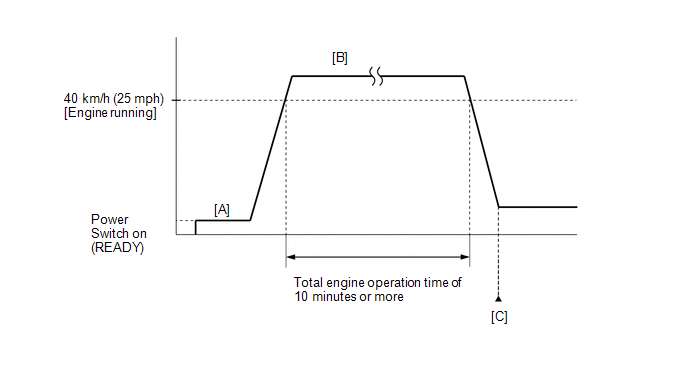
Fully depress the accelerator pedal for 10 seconds with the vehicle stopped, park (P) selected and the brake pedal depressed [A].
NOTICE:
As soon as the engine starts, release the accelerator pedal.
- Release the parking brake.
-
Drive the vehicle at an average of approximately 40 km/h (25 mph) or more until the total engine operation time is 10 minutes or more [B].
CAUTION:
When performing the confirmation driving pattern, obey all speed limits and traffic laws.
HINT:
- It is not necessary to maintain the vehicle speed at 40 km/h (25 mph) throughout the road test.
- If the engine stops, further depress the accelerator pedal to restart the engine.
- Enter the following menus: Powertrain / Engine and ECT / Trouble Codes [C].
-
Read the DTCs (including pending DTCs).
HINT:
- If a DTC (include pending DTC) is output, the system is malfunctioning.
- If a DTC (include pending DTC) is not output, perform the following procedure.
- Enter the following menus: Powertrain / Engine and ECT / Utility / All Readiness.
- Input the DTC: P3190 or P3191.
-
Check the DTC judgment result.
Techstream Display
Description
NORMAL
ABNORMAL
- DTC judgment completed
- System abnormal
INCOMPLETE
- DTC judgment not completed
- Perform driving pattern after confirming DTC enabling conditions
N/A
- Unable to perform DTC judgment
- Number of DTCs which do not fulfill DTC preconditions has reached ECU memory limit
HINT:
- If the judgment result shows NORMAL, the system is normal.
- If the judgment result shows ABNORMAL, the system has a malfunction.
- If the judgment result shows INCOMPLETE or N/A, perform the Confirmation Driving Pattern and check the DTC judgment result again.
-
If no DTC is output, perform a universal trip and check for permanent DTCs.
Click here
.gif)
HINT:
- If a permanent DTC is output, the system is malfunctioning.
- If no permanent DTC is output, the system is normal.
CAUTION / NOTICE / HINT
HINT:
- Repeating this inspection for symptom confirmation may cause the SOC to drop, preventing the system from entering the READY-on state. In this case, use the THS charger to charge the HV battery.
- Cranking the engine once causes the SOC to drop approximately 1%.
- Charging the HV battery once (10 minutes) using the THS charger restores the SOC approximately 2%.
- Charging the HV battery using the THS charger takes approximately 10 minutes when the HV battery temperature is 25°C (77°F) or approximately 30 minutes when the HV battery temperature is 0°C (32°F).
- The THS charger is a supplemental charging device that charges the HV battery enough to enable the engine to start (the vehicle can enter the READY-on state).
- Read freeze frame data using the Techstream. The ECM records vehicle and driving condition information as freeze frame data the moment a DTC is stored. When troubleshooting, freeze frame data can help determine if the vehicle was moving or stationary, if the engine was warmed up or not, if the air fuel ratio was lean or rich, and other data from the time the malfunction occurred.
PROCEDURE
| 1. | CHECK ANY OTHER DTCS OUTPUT (IN ADDITION TO DTC P3190, P3191 AND/OR P3193) |
(a) Connect the Techstream to the DLC3.
(b) Turn the power switch on (IG).
(c) Turn the Techstream on.
(d) Enter the following menus: Powertrain / Engine and ECT / Trouble Codes.
(e) Check the DTCs and freeze frame data, and then write them down.
Click here
| Result | Proceed to |
|---|---|
| DTC P3190 or P3191 are output | A |
| DTC P3193 is output | B |
| DTC P3190, P3191 and/or P3193 and other DTCs are output | C |
HINT:
If any SFI system DTCs other than DTC P3190, P3191 or P3193 is output, perform troubleshooting for those DTCs first.
| B | .gif) | GO TO DTC P3193 |
| C | | GO TO DTC CHART |
|
.gif)
| 2. | CHECK SHORTAGE OF FUEL |
(a) Check the amount of fuel remaining.
OK:
There is enough fuel.
HINT:
- DTCs P3190, P3191 and/or P3193 may be output if the vehicle ran out of fuel in the past.
- If not enough fuel is added, DTC P3190, P3191 or P3193 may be output again. If the engine cannot be started because the vehicle is out of fuel, add fuel until the fuel level warning light turns off.
| NG | | REFILL FUEL |
|
| 3. | CLEAR DTC |
(a) Connect the Techstream to the DLC3.
(b) Turn the power switch on (IG).
(c) Turn the Techstream on.
(d) Clear the DTCs.
Powertrain > Engine and ECT > Clear DTCs(e) Turn the power switch off and wait for at least 30 seconds.
|
| 4. | CHECK PCV HOSE CONNECTIONS |
(a) Check the PCV hose connections.
Click here
OK:
PCV valve and hose are connected correctly and are not damaged.
| NG | | REPAIR OR REPLACE PCV HOSE |
|
| 5. | CHECK INTAKE SYSTEM |
(a) Check the intake system for vacuum leaks.
Click here
OK:
No leaks in intake system.
HINT:
Perform "Inspection After Repair" after repairing or replacing the intake system.
Click here
| NG | | REPAIR OR REPLACE INTAKE SYSTEM |
|
| 6. | CHECK FOR UNUSUAL NOISE OR VIBRATION WHEN STARTING ENGINE OR REVVING UP |
OK:
Unusual noise and vibration do not occur.
| NG | | REPAIR OR REPLACE MALFUNCTIONING PARTS |
|
| 7. | CHECK FUEL PRESSURE |
(a) Check the fuel pressure.
Click here
| NG | | CHECK FUEL PUMP CONTROL CIRCUIT |
|
| 8. | INSPECT THROTTLE BODY WITH MOTOR ASSEMBLY |
(a) Inspect the throttle body with motor assembly.
Click here
HINT:
Perform "Inspection After Repair" after replacing the throttle body with motor assembly.
Click here
| NG | | REPLACE THROTTLE W/MOTOR BODY ASSEMBLY |
|
| 9. | INSPECT MASS AIR FLOW METER SUB-ASSEMBLY |
(a) Inspect the mass air flow meter sub-assembly.
Click here
HINT:
Perform "Inspection After Repair" after replacing the mass air flow meter sub-assembly.
Click here
| NG | | REPLACE INTAKE MASS AIR FLOW METER SUB-ASSEMBLY |
|
| 10. | INSPECT ENGINE COOLANT TEMPERATURE SENSOR |
(a) Inspect the engine coolant temperature sensor.
Click here
HINT:
Perform "Inspection After Repair" after replacing the engine coolant temperature sensor.
Click here
| NG | | REPLACE ENGINE COOLANT TEMPERATURE SENSOR |
|
| 11. | INSPECT CRANKSHAFT POSITION SENSOR |
(a) Inspect the crankshaft position sensor.
Click here
| NG | | REPLACE CRANKSHAFT POSITION SENSOR |
|
| 12. | PERFORM ACTIVE TEST USING TECHSTREAM (CONTROL THE EGR STEP POSITION) |
(a) Connect the Techstream to the DLC3.
(b) Turn the power switch on (IG).
(c) Turn the Techstream on.
(d) Put the engine in inspection mode (maintenance mode).
Click here
| Tester Display |
|---|
| Inspection Mode |
(e) Start the engine and warm it up until the engine coolant temperature reaches 75°C (167°F) or higher.
HINT:
The A/C switch and all accessory switches should be off.
(f) Enter the following menus: Powertrain / Engine and ECT / Active Test / Control the EGR Step Position / Primary / MAP and Throttle Idle Position.
Powertrain > Engine and ECT > Active Test| Active Test Display |
|---|
| Control the EGR Step Position |
| Data List Display |
|---|
| MAP |
| Throttle Idle Position |
(g) Confirm that the Throttle Idle Position is ON and check the MAP values in the Data List while performing the Active Test.
HINT:
- Do not leave the EGR valve open for 10 seconds or more during the Active Test.
- Be sure to return the EGR valve to step 0 when the Active Test is completed.
- Do not open the EGR valve 30 steps or more during the Active Test.
OK:
MAP change in response to EGR step position when Throttle Idle Position is ON in Data List.
Standard:
| - | EGR Step Position (Active Test) | |
|---|---|---|
| 0 Steps | 0 to 30 Steps | |
| MAP (Data List) | (EGR valve is fully closed) | MAP value is at least +10 kPa (75 mmHg) higher than when EGR valve is fully closed |
HINT:
- While performing the Active Test, if the increase in the value of MAP is small, the EGR valve assembly may be a malfunctioning.
- Even if the EGR valve assembly is malfunctioning, rough idling or an increase in the value of MAP may occur while performing the Active Test. However, the amount that the value of MAP increases will be smaller than normal.
- If there are starting problems and the Active Test cannot be performed, perform the EGR valve assembly inspection in the next step.
| OK | | GO TO STEP 14 |
|
| 13. | INSPECT EGR VALVE ASSEMBLY |
(a) Remove the EGR valve assembly.
Click here
(b) Check if the EGR valve is stuck open.
OK:
EGR valve is tightly closed.
HINT:
Perform "Inspection After Repair" after replacing the EGR valve assembly.
Click here
| NG | | REPLACE EGR VALVE ASSEMBLY |
|
| 14. | REPLACE CAMSHAFT POSITION SENSOR |
(a) Replace the camshaft position sensor.
Click here
|
| 15. | CHECK WHETHER DTC OUTPUT RECURS (DTC P3190 OR P3191) |
(a) Connect the Techstream to the DLC3.
(b) Turn the power switch on (IG).
(c) Turn the Techstream on.
(d) Clear the DTCs.
Powertrain > Engine and ECT > Clear DTCs(e) Turn the power switch off and wait for at least 30 seconds.
(f) Turn the power switch on (READY).
(g) Turn the Techstream on.
(h) Drive the vehicle in accordance with the driving pattern described in Confirmation Driving Pattern.
(i) Enter the following menus: Powertrain / Engine and ECT / Trouble Codes.
(j) Read the DTCs.
Click here
| Result | Proceed to |
|---|---|
| DTC P3190 or P3191 is output | A |
| DTCs are not output | B |
| B | | END |
|
| 16. | REPLACE ECM |
(a) Replace the ECM.
Click here
|
| 17. | CONFIRM WHETHER MALFUNCTION HAS BEEN SUCCESSFULLY REPAIRED |
(a) Connect the Techstream to the DLC3.
(b) Turn the power switch on (IG).
(c) Turn the Techstream on.
(d) Clear the DTCs.
Powertrain > Engine and ECT > Clear DTCs(e) Turn the power switch off and wait for 30 seconds.
(f) Turn the power switch on (READY).
(g) Turn the Techstream on.
(h) Drive the vehicle in accordance with the driving pattern described in Confirmation Driving Pattern.
(i) Enter the following menus: Powertrain / Engine and ECT / Trouble Codes.
(j) Read the DTCs.
Click here
| NEXT | | END |
READ NEXT:
 Fuel Run Out (P3193)
DESCRIPTION The ECM receives the fuel empty low level (below approximately 8.4 L) signal from the combination meter assembly (meter ECU) to detect if the vehicle is running out of fuel. DTC No. D
Lost Communication with Instrument Panel Cluster Control Module (Combination Meter) (U0155)
DESCRIPTION The ECM and combination meter assembly send and receiver signals via CAN communication. If a communication error occurs between the ECM and combination meter assembly, the ECM illuminates
Lost Communication with Hybrid Vehicle Control System (U0293)
MONITOR DESCRIPTION The ECM communicates with the hybrid vehicle control ECU. When the ECM does not receive data from the hybrid vehicle control ECU, the ECM illuminates the MIL and stores a DTC. D
SEE MORE:
Low Output Signal of Rear Speed Sensor RH (C1273,C1274,C1466,C1467)
DESCRIPTION Each speed sensor detects the wheel speed and sends the signals to the skid control ECU (brake booster with master cylinder assembly). These signals are used for ABS control. DTCs C1273 and C1274 are cleared when the speed sensor sends a wheel speed signal or when Test Mode ends. DTCs C1
Installation
INSTALLATION CAUTION / NOTICE / HINT HINT:
Use the same procedure for the LH side and RH side.
The following procedure is for the LH side.
PROCEDURE 1. INSTALL FRONT SKID CONTROL SENSOR WIRE LH (w/ AVS) (a) Install the sensor clamp as follows. (1) Install the grommet to the absorber brack
© 2016-2026 Copyright www.lexunx.com
