Lexus NX: Installation
INSTALLATION
CAUTION / NOTICE / HINT
HINT:
- Use the same procedure for the LH side and RH side.
- The following procedure is for the LH side.
PROCEDURE
1. INSTALL FRONT SKID CONTROL SENSOR WIRE LH (w/ AVS)
(a) Install the sensor clamp as follows.
| (1) Install the grommet to the absorber bracket. |
|
(2) Attach hook A of the sensor clamp to the absorber bracket.
NOTICE:
Do not twist the wire harness for the sensor clamp when installing it.
(3) Install the flexible hose clamp together with the skid control sensor clamp to the absorber bracket with the bolt.
Torque:
18.8 N·m {192 kgf·cm, 14 ft·lbf}
(4) Install the grommet to the absorber bracket.
(5) Connect the connector to the absorber control actuator.
(b) Install the sensor clamp to the side member with the bolt.
Torque:
8.5 N·m {87 kgf·cm, 75 in·lbf}
NOTICE:
Do not twist the wire harness for the sensor clamp when installing it.
(c) Install the clamp.
(d) Fold back the fender liner and connect the connector.
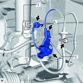
2. INSTALL FRONT SPEED SENSOR LH (w/ AVS)
| (a) Install the flexible hose clamp together with the sensor clamp with the bolt. Torque: 18.8 N·m {192 kgf·cm, 14 ft·lbf} NOTICE: Do not twist the wire harness for the sensor clamp when installing it. |
|
.png)
(b) Install the front speed sensor LH to the steering knuckle with the bolt.
Torque:
8.5 N·m {87 kgf·cm, 75 in·lbf}
NOTICE:
- Prevent foreign matter from attaching to the front speed sensor tip.
- Firmly insert the front speed sensor body into the steering knuckle before tightening the bolt.
(c) Connect the connector.
3. INSTALL FRONT SPEED SENSOR LH (w/o AVS)
(a) Install the front speed sensor LH to the steering knuckle with the bolt.
Torque:
8.5 N·m {87 kgf·cm, 75 in·lbf}
NOTICE:
- Prevent foreign matter from attaching to the front speed sensor tip.
- Firmly insert the front speed sensor body into the steering knuckle before tightening the bolt.
(b) Install the sensor clamp as follows.
| (1) Attach hook A and B of the sensor clamp to the flexible hose bracket. NOTICE: Do not twist the wire harness for the sensor clamp when installing it. |
|
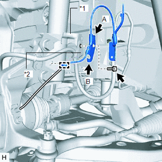
(2) Install the flexible hose clamp together with the sensor clamp to the absorber bracket with the bolt.
Torque:
18.8 N·m {192 kgf·cm, 14 ft·lbf}
(3) Install the clamp to the absorber bracket.
(c) Install the sensor clamp to the side member with the bolt.
Torque:
8.5 N·m {87 kgf·cm, 75 in·lbf}
NOTICE:
Do not twist the wire harness for the sensor clamp when installing it.
(d) Install the clamp.
(e) Fold back the fender liner and connect the connector.
4. INSTALL FRONT TIRE
Click here .gif)
5. CHECK FOR SPEED SENSOR SIGNAL
Click here
READ NEXT:
 Components
COMPONENTS ILLUSTRATION *A w/ AVS - - *1 REAR SPEED SENSOR LH - - N*m (kgf*cm, ft.*lbf): Specified torque - - ILLUSTRATION *A w/o AVS - - *1 REAR SPEE
Removal
REMOVAL CAUTION / NOTICE / HINT HINT:
Use the same procedure for the LH side and RH side.
The following procedure is for the LH side.
PROCEDURE 1. RELEASE PARKING BRAKE Click here 2. REMOVE
SEE MORE:
Lost Communication with Cruise Control Front Distance Range Sensor Missing Message (U023587,U0242)
DESCRIPTION DTC No. Detection Item DTC Detection Condition Trouble Area DTC Output from Note U023587 Lost Communication with Cruise Control Front Distance Range Sensor Missing Message
Power switch on (IG)
A communication malfunction with the millimeter wave radar sensor
Drive Motor "B" Control Module (P0A1C-713)
DESCRIPTION The MG ECU, which is built into the inverter with converter assembly, monitors its internal operation and will store DTCs if the system is malfunctioning. If any of the following DTCs are output, replace the inverter with converter assembly. DTC No. Detection Item DTC Detection Co
