Lexus NX: Power Window Switch Malfunction (B2312)
DESCRIPTION
The power window regulator motor assemblies are operated by the multiplex network master switch assembly, power window regulator switch assembly or rear power window regulator switch assemblies. The power window regulator motor assemblies have motor, regulator and ECU functions.
This DTC is output when an ECU built into a power window regulator motor assembly and multiplex network master switch assembly determines that the multiplex network master switch assembly, power window regulator switch assembly or rear power window regulator switch assembly is stuck.
Master Switch| DTC No. | Detection Item | DTC Detection Condition | Trouble Area |
|---|---|---|---|
| B2312 | Power Window Switch Malfunction |
| Multiplex network master switch assembly |
| DTC No. | Detection Item | DTC Detection Condition | Trouble Area |
|---|---|---|---|
| B2312 | Power Window Switch Malfunction |
|
|
| DTC No. | Detection Item | DTC Detection Condition | Trouble Area |
|---|---|---|---|
| B2312 | Power Window Switch Malfunction |
|
|
| DTC No. | Detection Item | DTC Detection Condition | Trouble Area |
|---|---|---|---|
| B2312 | Power Window Switch Malfunction |
|
|
| DTC No. | Detection Item | DTC Detection Condition | Trouble Area |
|---|---|---|---|
| B2312 | Power Window Switch Malfunction |
|
|
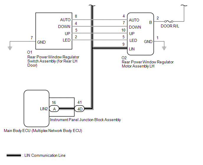
WIRING DIAGRAM
.png)
CAUTION / NOTICE / HINT
NOTICE:
- DTC B2312 is stored in the multiplex network master switch assembly and in each power window regulator motor assembly.
-
If a power window regulator motor assembly has been replaced with a new one, initialize the power window control system.
Click here
.gif)
- Inspect the fuses for circuits related to this system before performing the following procedure.
-
The power window control system uses the LIN communication system. Inspect the communication function by following How to Proceed with Troubleshooting. Troubleshoot the power window control system after confirming that the communication system is functioning properly.
Click here
HINT:
If DTC B2312 is not output again after the DTC has been cleared, the DTC was output due to the switch being held.
PROCEDURE
| 1. | CHECK FOR DTC |
(a) Clear the DTCs.
Click here
(b) Check for DTCs.
Click here
OK:
DTC B2312 is not output.
| OK | .gif) | END (DUE TO SWITCH BEING OPERATED FOR 20 SECONDS OR MORE) |
|
.gif)
| 2. | CHECK FOR DTC |
(a) Check the parts which the DTCs have been output from.
| Result | Proceed to |
|---|---|
| DTC output from Master Switch | A |
| DTC output from D-Door Motor | B |
| DTC output from P-Door Motor | C |
| DTC output from RL-Door Motor | D |
| DTC output from RR-Door Motor | E |
| A | | REPLACE MULTIPLEX NETWORK MASTER SWITCH ASSEMBLY |
| C | | GO TO STEP 7 |
| D | | GO TO STEP 10 |
| E | | GO TO STEP 13 |
|
| 3. | READ VALUE USING TECHSTREAM (D-DOOR MOTOR) |
(a) Read the Data List according to the display on the Techstream.
Click here
| Tester Display | Measurement Item | Range | Normal Condition | Diagnostic Note |
|---|---|---|---|---|
| D Door P/W Up SW | Driver door power window manual up switch signal | OFF or ON | OFF: Driver door power window manual up switch not being operated ON: Driver door power window manual up switch being operated | - |
| D Door P/W Down SW | Driver door power window manual down switch signal | OFF or ON | OFF: Driver door power window manual down switch not being operated ON: Driver door power window manual down switch being operated | - |
| Tester Display |
|---|
| D Door P/W Up SW |
| D Door P/W Down SW |
OK:
On the Techstream screen, ON or OFF is displayed accordingly.
| OK | | REPLACE FRONT POWER WINDOW REGULATOR MOTOR ASSEMBLY LH |
|
| 4. | CHECK HARNESS AND CONNECTOR (MULTIPLEX NETWORK MASTER SWITCH ASSEMBLY - FRONT POWER WINDOW REGULATOR MOTOR ASSEMBLY LH) |
(a) Disconnect the M10 multiplex network master switch assembly connector.
(b) Disconnect the M2 front power window regulator motor assembly LH connector.
(c) Measure the resistance according to the value(s) in the table below.
Standard Resistance:
| Tester Connection | Condition | Specified Condition |
|---|---|---|
| M10-20 (UP) - Body ground | Always | 10 kΩ or higher |
| M10-15 (DOWN) - Body ground | Always | 10 kΩ or higher |
| M2-10 (UP) - Body ground | Always | 10 kΩ or higher |
| M2-7 (DOWN) - Body ground | Always | 10 kΩ or higher |
| NG | | REPAIR OR REPLACE HARNESS OR CONNECTOR |
|
| 5. | REPLACE MULTIPLEX NETWORK MASTER SWITCH ASSEMBLY |
(a) Replace the multiplex network master switch assembly.
Click here
|
| 6. | CHECK FOR DTC |
(a) Clear the DTCs.
Click here
(b) Check for DTCs.
Click here
OK:
DTC B2312 is not output.
| OK | | END (MULTIPLEX NETWORK MASTER SWITCH ASSEMBLY WAS DEFECTIVE) |
| NG | | REPLACE FRONT POWER WINDOW REGULATOR MOTOR ASSEMBLY LH |
| 7. | READ VALUE USING TECHSTREAM (P-DOOR MOTOR) |
(a) Read the Data List according to the display on the Techstream.
Click here
| Tester Display | Measurement Item | Range | Normal Condition | Diagnostic Note |
|---|---|---|---|---|
| P Door P/W Auto SW | Front passenger door power window auto switch signal | OFF or ON | OFF: Front passenger door power window auto switch not being operated ON: Front passenger door power window auto switch being operated | - |
| P Door P/W Up SW | Front passenger door power window manual up switch signal | OFF or ON | OFF: Front passenger door power window manual up switch not being operated ON: Front passenger door power window manual up switch being operated | - |
| P Door P/W Down SW | Front passenger door power window manual down switch signal | OFF or ON | OFF: Front passenger door power window manual down switch not being operated ON: Front passenger door power window manual down switch being operated | - |
| Tester Display |
|---|
| P Door P/W Auto SW |
| P Door P/W Up SW |
| P Door P/W Down SW |
OK:
On the Techstream screen, ON or OFF is displayed accordingly.
| OK | | REPLACE FRONT POWER WINDOW REGULATOR MOTOR ASSEMBLY RH |
|
| 8. | INSPECT POWER WINDOW REGULATOR SWITCH ASSEMBLY |
(a) Remove the power window regulator switch assembly.
Click here
(b) Inspect the power window regulator switch assembly.
Click here
| NG | | REPLACE POWER WINDOW REGULATOR SWITCH ASSEMBLY |
|
| 9. | CHECK HARNESS AND CONNECTOR (POWER WINDOW REGULATOR SWITCH ASSEMBLY - FRONT POWER WINDOW REGULATOR MOTOR ASSEMBLY RH) |
(a) Disconnect the L11 power window regulator switch assembly connector.
(b) Disconnect the L2 front power window regulator motor assembly RH connector.
(c) Measure the resistance according to the value(s) in the table below.
Standard Resistance:
| Tester Connection | Condition | Specified Condition |
|---|---|---|
| L11-5 (UP) - Body ground | Always | 10 kΩ or higher |
| L11-8 (AUTO) - Body ground | Always | 10 kΩ or higher |
| L11-4 (DOWN) - Body ground | Always | 10 kΩ or higher |
| L2-10 (UP) - Body ground | Always | 10 kΩ or higher |
| L2-4 (AUTO) - Body ground | Always | 10 kΩ or higher |
| L2-7 (DOWN) - Body ground | Always | 10 kΩ or higher |
| OK | | REPLACE FRONT POWER WINDOW REGULATOR MOTOR ASSEMBLY RH |
| NG | | REPAIR OR REPLACE HARNESS OR CONNECTOR |
| 10. | READ VALUE USING TECHSTREAM (RL-DOOR MOTOR) |
(a) Read the Data List according to the display on the Techstream.
Click here
| Tester Display | Measurement Item | Range | Normal Condition | Diagnostic Note |
|---|---|---|---|---|
| RL Door P/W Auto SW | Rear LH door power window auto switch signal | OFF or ON | OFF: Rear LH door power window auto switch not being operated ON: Rear LH door power window auto switch being operated | - |
| RL Door P/W Up SW | Rear LH door power window manual up switch signal | OFF or ON | OFF: Rear LH door power window manual up switch not being operated ON: Rear LH door power window manual up switch being operated | - |
| RL Door P/W Down SW | Rear LH door power window manual down switch signal | OFF or ON | OFF: Rear LH door power window manual down switch not being operated ON: Rear LH door power window manual down switch being operated | - |
| Tester Display |
|---|
| RL Door P/W Auto SW |
| RL Door P/W Up SW |
| RL Door P/W Down SW |
OK:
On the Techstream screen, ON or OFF is displayed accordingly.
| OK | | REPLACE REAR POWER WINDOW REGULATOR MOTOR ASSEMBLY LH |
|
| 11. | INSPECT REAR POWER WINDOW REGULATOR SWITCH ASSEMBLY (FOR REAR LH DOOR) |
(a) Remove the rear power window regulator switch assembly (for rear LH door).
Click here
(b) Inspect the rear power window regulator switch assembly (for rear LH door).
Click here
| NG | | REPLACE REAR POWER WINDOW REGULATOR SWITCH ASSEMBLY (FOR REAR LH DOOR) |
|
| 12. | CHECK HARNESS AND CONNECTOR (REAR POWER WINDOW REGULATOR SWITCH ASSEMBLY [FOR REAR LH DOOR] - REAR POWER WINDOW REGULATOR MOTOR ASSEMBLY LH) |
(a) Disconnect the O1 rear power window regulator switch assembly (for rear LH door) connector.
(b) Disconnect the O2 rear power window regulator motor assembly LH connector.
(c) Measure the resistance according to the value(s) in the table below.
Standard Resistance:
| Tester Connection | Condition | Specified Condition |
|---|---|---|
| O1-5 (UP) - Body ground | Always | 10 kΩ or higher |
| O1-4 (DOWN) - Body ground | Always | 10 kΩ or higher |
| O1-8 (AUTO) - Body ground | Always | 10 kΩ or higher |
| O2-10 (UP) - Body ground | Always | 10 kΩ or higher |
| O2-7 (DOWN) - Body ground | Always | 10 kΩ or higher |
| O2-4 (AUTO) - Body ground | Always | 10 kΩ or higher |
| OK | | REPLACE REAR POWER WINDOW REGULATOR MOTOR ASSEMBLY LH |
| NG | | REPAIR OR REPLACE HARNESS OR CONNECTOR |
| 13. | READ VALUE USING TECHSTREAM (RR-DOOR MOTOR) |
(a) Read the Data List according to the display on the Techstream.
Click here
| Tester Display | Measurement Item | Range | Normal Condition | Diagnostic Note |
|---|---|---|---|---|
| RR Door P/W Auto SW | Rear RH door power window auto switch signal | OFF or ON | OFF: Rear RH door power window auto switch not being operated ON: Rear RH door power window auto switch being operated | - |
| RR Door P/W Up SW | Rear RH door power window manual up switch signal | OFF or ON | OFF: Rear RH door power window manual up switch not being operated ON: Rear RH door power window manual up switch being operated | - |
| RR Door P/W Down SW | Rear RH door power window manual down switch signal | OFF or ON | OFF: Rear RH door power window manual down switch not being operated ON: Rear RH door power window manual down switch being operated | - |
| Tester Display |
|---|
| RR Door P/W Auto SW |
| RR Door P/W Up SW |
| RR Door P/W Down SW |
OK:
On the Techstream screen, ON or OFF is displayed accordingly.
| OK | | REPLACE REAR POWER WINDOW REGULATOR MOTOR ASSEMBLY RH |
|
| 14. | INSPECT REAR POWER WINDOW REGULATOR SWITCH ASSEMBLY (FOR REAR RH DOOR) |
(a) Remove the rear power window regulator switch assembly (for rear RH door).
Click here
(b) Inspect the rear power window regulator switch assembly (for rear RH door).
Click here
| NG | | REPLACE REAR POWER WINDOW REGULATOR SWITCH ASSEMBLY (FOR REAR RH DOOR) |
|
| 15. | CHECK HARNESS AND CONNECTOR (REAR POWER WINDOW REGULATOR SWITCH ASSEMBLY [FOR REAR RH DOOR] - REAR POWER WINDOW REGULATOR MOTOR ASSEMBLY RH) |
(a) Disconnect the N1 rear power window regulator switch assembly (for rear RH door) connector.
(b) Disconnect the N2 rear power window regulator motor assembly RH connector.
(c) Measure the resistance according to the value(s) in the table below.
Standard Resistance:
| Tester Connection | Condition | Specified Condition |
|---|---|---|
| N1-5 (UP) - Body ground | Always | 10 kΩ or higher |
| N1-4 (DOWN) - Body ground | Always | 10 kΩ or higher |
| N1-8 (AUTO) - Body ground | Always | 10 kΩ or higher |
| N2-10 (UP) - Body ground | Always | 10 kΩ or higher |
| N2-7 (DOWN) - Body ground | Always | 10 kΩ or higher |
| N2-4 (AUTO) - Body ground | Always | 10 kΩ or higher |
| OK | | REPLACE REAR POWER WINDOW REGULATOR MOTOR ASSEMBLY RH |
| NG | | REPAIR OR REPLACE HARNESS OR CONNECTOR |
READ NEXT:
 Glass Position Initialization Incomplete (B2313)
DESCRIPTION The power window regulator motor assemblies are operated by the multiplex network master switch assembly, power window regulator switch assembly or rear power window regulator switch assem
Remote Up / Down Function does not Operate
DESCRIPTION When the power switch is on (IG), the multiplex network master switch assembly sends remote up and down signals to each power window regulator motor assembly via LIN communication. WIRING
Driver Side Power Window does not Operate with Power Window Master Switch
DESCRIPTION When the power switch is on (IG), the front power window regulator motor assembly LH is operated by the multiplex network master switch assembly. The front power window regulator motor ass
SEE MORE:
Precaution
PRECAUTION PRECAUTION FOR DISCONNECTING CABLE FROM NEGATIVE AUXILIARY BATTERY TERMINAL NOTICE: When disconnecting and reconnecting the auxiliary battery. Click here HINT: When disconnecting and reconnecting the auxiliary battery, there is an automatic learning function that completes learning when
Components
COMPONENTS ILLUSTRATION *1 DECK FLOOR BOX LH *2 NO. 3 DECK BOARD SUB-ASSEMBLY *3 REAR DECK FLOOR BOX *4 NEGATIVE AUXILIARY BATTERY TERMINAL N*m (kgf*cm, ft.*lbf): Specified torque - - ILLUSTRATION *1 BATTERY SERVICE HOLE COVER *2 HYBRID BATTERY SERVICE PLU
