Lexus NX: Driver Side Power Window does not Operate with Power Window Master Switch
DESCRIPTION
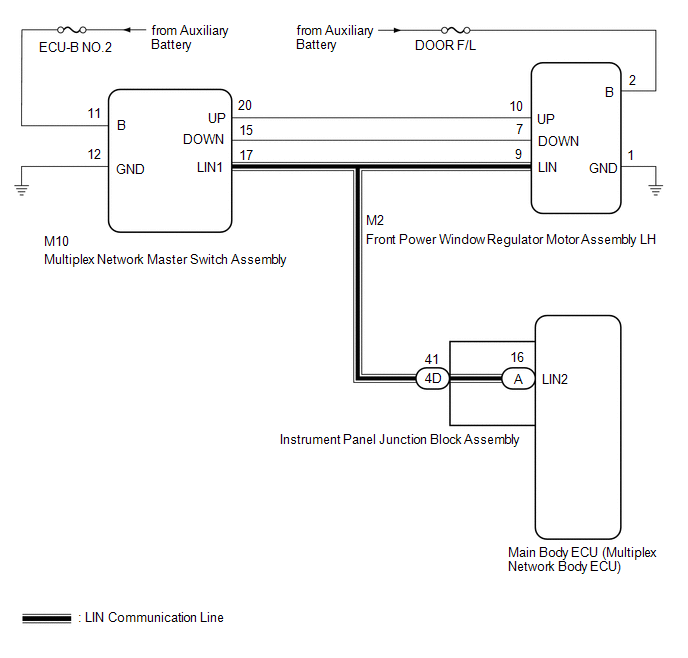
When the power switch is on (IG), the front power window regulator motor assembly LH is operated by the multiplex network master switch assembly. The front power window regulator motor assembly LH has motor, regulator and ECU functions.
WIRING DIAGRAM
CAUTION / NOTICE / HINT
NOTICE:
-
The power window control system uses the LIN communication system. Inspect the communication function by following How to Proceed with Troubleshooting. Troubleshoot the power window control system after confirming that the communication system is functioning properly.
Click here
.gif)
-
If the front power window regulator motor assembly LH has been replaced with a new one, initialize the power window control system.
Click here
- Inspect the fuses for circuits related to this system before performing the following procedure.
- Recognition code registration is necessary when replacing the main body ECU (multiplex network body ECU).
-
If the main body ECU (multiplex network body ECU) is replaced, refer to Registration.
Click here
PROCEDURE
| 1. | READ VALUE USING TECHSTREAM (MAIN BODY) |
(a) Read the Data List according to the display on the Techstream.
Click here
| Tester Display | Measurement Item | Range | Normal Condition | Diagnostic Note |
|---|---|---|---|---|
| Communication D-Door Motor | Connection status between front power window regulator motor assembly LH and main body ECU (multiplex network body ECU) | STOP or OK | STOP: Communication stopped OK: Normal communication | - |
| Communication Master SW | Connection status between multiplex network master switch assembly and main body ECU (multiplex network body ECU) | STOP or OK | STOP: Communication stopped OK: Normal communication | - |
| Tester Display |
|---|
| Communication D-Door Motor |
| Communication Master SW |
OK:
On the Techstream screen, OK is displayed.
| NG | .gif) | GO TO LIN COMMUNICATION SYSTEM |
|
.gif)
| 2. | READ VALUE USING TECHSTREAM (D-DOOR MOTOR) |
(a) Read the Data List according to the display on the Techstream.
Click here
| Tester Display | Measurement Item | Range | Normal Condition | Diagnostic Note |
|---|---|---|---|---|
| D Door P/W Up SW | Driver door power window manual up switch signal | OFF or ON | OFF: Driver door power window manual up switch not being operated ON: Driver door power window manual up switch being operated | - |
| D Door P/W Down SW | Driver door power window manual down switch signal | OFF or ON | OFF: Driver door power window manual down switch not being operated ON: Driver door power window manual down switch being operated | - |
| Tester Display |
|---|
| D Door P/W Up SW |
| D Door P/W Down SW |
OK:
On the Techstream screen, ON or OFF is displayed accordingly.
| NG | | GO TO STEP 4 |
|
| 3. | PERFORM ACTIVE TEST USING TECHSTREAM (D-DOOR MOTOR) |
(a) Perform the Active Test according to the display on the Techstream.
Click here
CAUTION:
Be careful to avoid injuries as this test causes vehicle parts to move. During the Active Test, the jam protection function will not operate.
Body Electrical > D-Door Motor > Active Test| Tester Display | Measurement Item | Control Range | Diagnostic Note |
|---|---|---|---|
| Power Window | Power window | OFF / DOWN / UP | - |
| Tester Display |
|---|
| Power Window |
HINT:
Up and down movement does not occur if the arrow is not pressed and held.
OK:
Driver door power window operates normally.
| OK | | REPLACE MAIN BODY ECU (MULTIPLEX NETWORK BODY ECU) |
| NG | | REPLACE FRONT POWER WINDOW REGULATOR MOTOR ASSEMBLY LH |
| 4. | CHECK HARNESS AND CONNECTOR (MULTIPLEX NETWORK MASTER SWITCH ASSEMBLY - FRONT POWER WINDOW REGULATOR MOTOR ASSEMBLY LH) |
(a) Disconnect the M10 multiplex network master switch assembly connector.
(b) Disconnect the M2 front power window regulator motor assembly LH connector.
(c) Measure the resistance according to the value(s) in the table below.
Standard Resistance:
| Tester Connection | Condition | Specified Condition |
|---|---|---|
| M10-20 (UP) - M2-10 (UP) | Always | Below 1 Ω |
| M10-15 (DOWN) - M2-7 (DOWN) | Always | Below 1 Ω |
| M10-20 (UP) or M2-10 (UP) - Body ground | Always | 10 kΩ or higher |
| M10-15 (DOWN) or M2-7 (DOWN) - Body ground | Always | 10 kΩ or higher |
| NG | | REPAIR OR REPLACE HARNESS OR CONNECTOR |
|
| 5. | REPLACE MULTIPLEX NETWORK MASTER SWITCH ASSEMBLY |
(a) Replace the multiplex network master switch assembly.
Click here
|
| 6. | CHECK MANUAL UP / DOWN FUNCTION (FOR DRIVER DOOR) |
(a) Check that the driver door power window moves when the manual up and down function of the power window regulator master switch assembly is operated.
Click here
OK:
Driver door manual up and down function is normal.
| OK | | END (MULTIPLEX NETWORK MASTER SWITCH ASSEMBLY WAS DEFECTIVE) |
| NG | | REPLACE FRONT POWER WINDOW REGULATOR MOTOR ASSEMBLY LH |
READ NEXT:
 Front Passenger Side Power Window does not Operate with Front Passenger Side Power Window Switch
DESCRIPTION When the power switch is on (IG), the front power window regulator motor assembly RH is operated by the power window regulator switch assembly. The front power window regulator motor assem
Rear Power Window RH does not Operate with Rear Power Window Switch RH
DESCRIPTION When the power switch is on (IG), the rear power window regulator motor assembly RH is operated by the rear power window regulator switch assembly (for rear RH door). The rear power window
Driver Side Power Window Auto Up / Down Function does not Operate with Power Window Master Switch
DESCRIPTION If the manual up and down function operates normally but the auto up and down function does not, then fail-safe mode may be functioning. If power window initialization has not been perform
SEE MORE:
Precaution
PRECAUTION PRECAUTION FOR DISCONNECTING CABLE FROM NEGATIVE AUXILIARY BATTERY TERMINAL NOTICE:
After the power switch is turned off, there may be a waiting time before disconnecting the negative (-) auxiliary battery terminal.
Click here
When disconnecting and reconnecting the auxiliary batte
Components
COMPONENTS ILLUSTRATION *1 EGR COOLER ASSEMBLY *2 EGR VALVE ASSEMBLY *3 FUEL DELIVERY PIPE *4 INJECTOR VIBRATION INSULATOR *5 INTAKE MANIFOLD *6 NO. 1 EGR PIPE *7 NO. 1 WATER BY-PASS HOSE *8 NO. 3 WATER BY-PASS HOSE *9 THROTTLE WITH MOTOR BODY ASSEMBLY
