Lexus NX: Parts Location
PARTS LOCATION
ILLUSTRATION
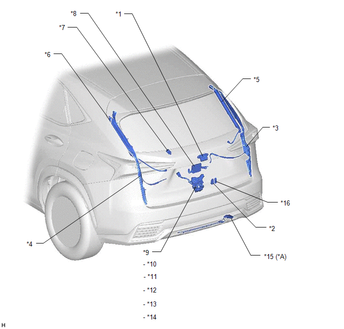
| *A | w/ Hands Free Power Back Door | - | - |
| *1 | BACK DOOR OPENER SWITCH ASSEMBLY | *2 | BACK DOOR CONTROL SWITCH |
| *3 | POWER BACK DOOR SENSOR ASSEMBLY RH | *4 | POWER BACK DOOR SENSOR ASSEMBLY LH |
| *5 | POWER BACK DOOR UNIT ASSEMBLY SET RH | *6 | POWER BACK DOOR UNIT ASSEMBLY SET LH |
| *7 | POWER BACK DOOR WARNING BUZZER | *8 | MULTIPLEX NETWORK DOOR ECU |
| *9 | BACK DOOR LOCK ASSEMBLY | *10 | BACK DOOR LOCK MOTOR |
| *11 | BACK DOOR COURTESY SWITCH | *12 | LATCH SWITCH |
| *13 | INITIAL SWITCH | *14 | PAWL SWITCH |
| *15 | KICK DOOR CONTROL SENSOR | *16 | DOOR CONTROL SWITCH |
ILLUSTRATION
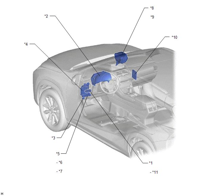
| *1 | COMBINATION SWITCH ASSEMBLY | *2 | COMBINATION METER ASSEMBLY |
| *3 | DLC3 | *4 | MAIN BODY ECU (MULTIPLEX NETWORK BODY ECU) |
| *5 | INSTRUMENT PANEL JUNCTION BLOCK ASSEMBLY | *6 | PBD FUSE |
| *7 | ECU-IG NO.1 FUSE | *8 | ENGINE ROOM RELAY BLOCK |
| *9 | ECU-B NO.1 FUSE | *10 | CERTIFICATION ECU (SMART KEY ECU ASSEMBLY) |
| *11 | POWER BACK DOOR SWITCH | - | - |
READ NEXT:
 System Diagram
SYSTEM DIAGRAM Communication Table Transmitting ECU Receiving ECU Signal Communication Method Main body ECU (multiplex network body ECU) Multiplex network door ECU
Combination s
System Description
SYSTEM DESCRIPTION POWER BACK DOOR SYSTEM DESCRIPTION (a) The power back door system controls the power back door by automatically opening and closing the power back door with a motor. (1) The power b
How To Proceed With Troubleshooting
CAUTION / NOTICE / HINT HINT:
The power back door system troubleshooting procedure is based on the premise that the smart access system with push-button start (for Entry Function) is operating norm
SEE MORE:
Rear Power Window Switch
ComponentsCOMPONENTS ILLUSTRATION *1 REAR POWER WINDOW REGULATOR SWITCH ASSEMBLY *2 REAR POWER WINDOW REGULATOR SWITCH ASSEMBLY WITH REAR DOOR ARMREST BASE PANEL *3 REAR DOOR ARMREST BASE PANEL - - RemovalREMOVAL CAUTION / NOTICE / HINT HINT:
Use the same procedure for th
Inspection
INSPECTION PROCEDURE 1. INSPECT WINDSHIELD WASHER MOTOR AND PUMP ASSEMBLY (for Front Side) HINT: This check should be performed with the windshield washer motor and pump assembly installed to the windshield washer jar assembly. (a) With the windshield washer motor and pump assembly installed to the
