Lexus NX: Reassembly
REASSEMBLY
CAUTION / NOTICE / HINT
NOTICE:
- When using a vise, place aluminum plates between the part and vise.
- When using a vise, do not overtighten it.
PROCEDURE
1. INSTALL POWER STEERING MOTOR ASSEMBLY
NOTICE:
- Do not drop the power steering ECU with motor assembly, strike it with tools or subject it to impacts.
- If the power steering ECU with motor assembly is subjected to an impact, replace it with a new one.
- Do not pull the wire harness of the power steering ECU with motor assembly.
- Do not allow any moisture to come into contact with the power steering ECU with motor assembly.
- Do not loosen any bolts not mentioned in the procedure.
- Do not allow any foreign matter to contaminate the power steering ECU with motor assembly.
(a) Apply grease to the spline part of the power steering motor assembly.
| (b) Install the power steering motor assembly with the 2 bolts. Torque: 20 N·m {204 kgf·cm, 15 ft·lbf} |
|
.png)
(c) Place new heat resistant tape.
NOTICE:
As heat from the power steering motor assembly may generate smoke, use heat resistant tape (resistant to 100°C (212°F) or higher).
2. INSTALL POWER STEERING ECU ASSEMBLY
Click here .gif)
3. INSTALL WIRE HARNESS BRACKET
(a) Push in the direction shown in the illustration to attach the guide.
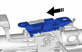
.png) | Install in this Direction |
(b) Push down in the direction (1) indicated by the arrow shown in the illustration, and push in direction (2) to attach the claw and install the bracket to the steering column assembly.
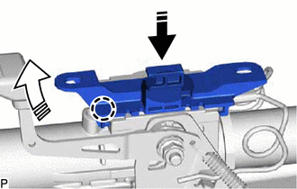
| | Install in this Direction (1) |
.png) | Install in this Direction (2) |
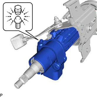
4. INSTALL STEERING LOCK ACTUATOR ASSEMBLY
HINT:
When replacing the steering lock actuator assembly, refer to the Service Bulletin.
(a) Temporarily install the steering lock actuator assembly with a new tapered-head bolt.
NOTICE:
Be sure to use a new tapered-head bolt.
| (b) Tighten the tapered-head bolt until the bolt head breaks off. |
|
READ NEXT:
 Installation
INSTALLATION CAUTION / NOTICE / HINT NOTICE:
Do not replace the spiral with sensor cable sub-assembly with the battery connected and the engine switch on (IG).
Do not rotate the spiral with senso
Components
COMPONENTS ILLUSTRATION *1 COLUMN HOLE COVER SILENCER SHEET *2 COMBINATION SWITCH ASSEMBLY WITH SPIRAL CABLE SUB-ASSEMBLY *3 ELECTRIC POWER STEERING COLUMN SUB-ASSEMBLY *4 NO. 1 AI
SEE MORE:
Test Mode Procedure
TEST MODE PROCEDURE REAR BRAKE PAD REPLACEMENT MODE *1 Rear Disc Brake Piston *2 Nut *a Move nut back inside using pad replacement mode HINT: When replacing the rear disc brake pad and rear disc, since the nut inside the rear disc brake cylinder assembly is in an advanced positi
Installation
INSTALLATION PROCEDURE 1. INSTALL WINDSHIELD WIPER RELAY ASSEMBLY (a) Attach the 2 claws to install the windshield wiper relay assembly. 2. INSTALL ECU INTEGRATION BOX RH Click here 3. INSTALL NO. 2 INSTRUMENT PANEL UNDER COVER SUB-ASSEMBLY Click here 4. INSTALL GLOVE COMPARTMENT DOOR ASSEMBLY C
