Lexus NX: Components
COMPONENTS
ILLUSTRATION
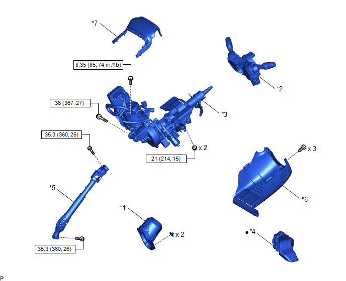
| *1 | COLUMN HOLE COVER SILENCER SHEET | *2 | COMBINATION SWITCH ASSEMBLY WITH SPIRAL CABLE SUB-ASSEMBLY |
| *3 | ELECTRIC POWER STEERING COLUMN SUB-ASSEMBLY | *4 | NO. 1 AIR DUCT |
| *5 | NO. 2 STEERING INTERMEDIATE SHAFT ASSEMBLY | *6 | LOWER STEERING COLUMN COVER |
| *7 | UPPER STEERING COLUMN COVER | - | - |
.png) | N*m (kgf*cm, ft.*lbf): Specified | ● | Non-reusable part |
ILLUSTRATION
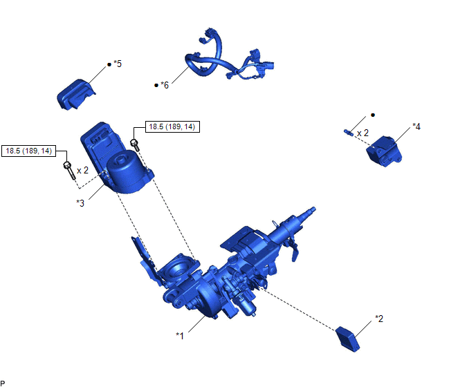
| *1 | ELECTRIC POWER STEERING COLUMN SUB-ASSEMBLY | *2 | MULTIPLEX TILT AND TELESCOPIC ECU |
| *3 | POWER STEERING ECU ASSEMBLY | *4 | STEERING LOCK ACTUATOR ASSEMBLY |
| *5 | POWER STEERING ECU PROTECTOR | *6 | ECU WIRE SUB-ASSEMBLY |
| | N*m (kgf*cm, ft.*lbf): Specified | ● | Non-reusable part |
READ NEXT:
 Removal
REMOVAL CAUTION / NOTICE / HINT NOTICE:
Do not replace the spiral with sensor cable sub-assembly with the battery connected and the power switch on (IG).
Do not rotate the spiral with sensor cabl
Disassembly
DISASSEMBLY CAUTION / NOTICE / HINT NOTICE:
When using a vise, place aluminum plates between the part and vise.
When using a vise, do not overtighten it.
PROCEDURE 1. REMOVE STEERING LOCK ACTU
Inspection
INSPECTION CAUTION / NOTICE / HINT NOTICE:
When using a vise, place aluminum plates between the part and vise.
When using a vise, do not overtighten it.
PROCEDURE 1. INSPECT ELECTRIC POWER STE
SEE MORE:
Power Back Door cannot be Opened or Closed Using the Power Back Door Switch
DESCRIPTION When the power back door cannot be opened or closed using the combination switch assembly, one of the following may be malfunctioning: 1) combination switch assembly circuit, 2) multiplex network door ECU or 3) main body ECU (multiplex network body ECU). WIRING DIAGRAM CAUTION / NOTICE
D-Seat ECU Vehicle Information Reading/Writing Process Malfunction (B15F8)
DESCRIPTION This DTC is stored when items controlled by the position control ECU assembly (driver seat) cannot be customized via the audio and visual system vehicle customization screen. HINT: The position control ECU assembly (driver seat) controls the front power seat control system (w/ Memory) re
© 2016-2026 Copyright www.lexunx.com
