Lexus NX: Reassembly
REASSEMBLY
CAUTION / NOTICE / HINT
HINT:
- Use the same procedure for the RH and LH sides.
- The following procedure is for the LH side.
PROCEDURE
1. TEMPORARILY INSTALL FRONT DISC BRAKE BLEEDER PLUG
(a) Temporarily install the front disc brake bleeder plug to the disc brake cylinder assembly LH.
HINT:
The front disc brake bleeder plug will be tightened to a torque specification in the "Bleed Brake Line" procedures.
2. INSTALL FRONT DISC BRAKE BLEEDER PLUG CAP
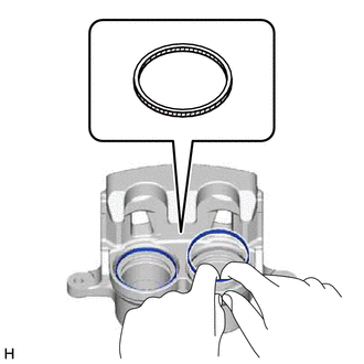
3. INSTALL PISTON SEAL
(a) Apply a light coat of lithium soap base glycol grease to the entire inner and outer circumference of 2 new piston seals.
 | Lithium soap base glycol grease |
(b) Install the 2 piston seals to the disc brake cylinder assembly LH.
NOTICE:
Securely install the piston seal into the groove of the disc brake cylinder assembly LH.
4. INSTALL FRONT DISC BRAKE PISTON
(a) Apply a light coat of lithium soap base glycol grease to the inner and outer circumference of 2 new cylinder boots, as well as the entire circumference of the top and bottom of the outer edge as shown in the illustration.
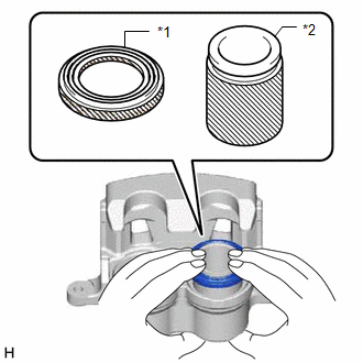
| *1 | Cylinder Boot |
| *2 | Front Disc Brake Piston |
| | Lithium soap base glycol grease |
(b) Apply a light coat of lithium soap base glycol grease to the entire outer circumference of the front disc brake piston where it contacts the 2 cylinder boots and disc brake cylinder assembly LH.
(c) Install the 2 cylinder boots to the front disc brake piston.
NOTICE:
Do not install the front disc brake piston forcibly in the disc brake cylinder assembly LH.
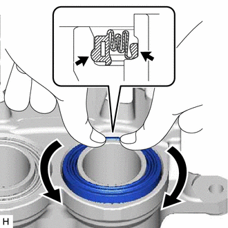
5. INSTALL CYLINDER BOOT
| (a) Install the 2 cylinder boots to the disc brake cylinder assembly LH as shown in the illustration. NOTICE:
|
|
READ NEXT:
 Installation
INSTALLATION CAUTION / NOTICE / HINT HINT:
Use the same procedure for the RH and LH sides.
The following procedure is for the LH side.
NOTICE: When the brake pedal is first depressed after rep
Components
COMPONENTS ILLUSTRATION *1 DECK FLOOR BOX LH *2 NO. 3 DECK BOARD SUB-ASSEMBLY *3 REAR DECK FLOOR BOX *4 NEGATIVE AUXILIARY BATTERY TERMINAL N*m (kgf*cm, ft.*lbf): Specified
SEE MORE:
Precaution
PRECAUTION HANDLING PRECAUTIONS FOR SRS AIRBAG SYSTEM (a) This vehicle is equipped with a Supplemental Restraint System (SRS). Failure to carry out service operations in the correct sequence could cause the SRS to unexpectedly deploy during servicing. This may cause a serious accident. Before servic
Terminals Of Ecu
TERMINALS OF ECU *a Component with harness connected (Power Steering ECU Assembly) - - CHECK POWER STEERING ECU ASSEMBLY (a) Measure the voltage and resistance according to the value(s) in the table below. NOTICE: When the power steering warning light (red) is illuminated due to a malfu
