Lexus NX: Installation
INSTALLATION
CAUTION / NOTICE / HINT
HINT:
- Use the same procedure for the RH and LH sides.
- The following procedure is for the LH side.
NOTICE:
When the brake pedal is first depressed after replacing the brake pads or pushing back the disc brake piston, DTC C1214 may be output. As there is no malfunction, clear the DTCs.
PROCEDURE
1. INSTALL FRONT DISC
| (a) Align the matchmarks and install the front disc. HINT: When replacing the disc with a new one, select the installation position where the front disc has smallest runout. |
|
.png)
2. INSTALL FRONT DISC BRAKE CYLINDER MOUNTING LH
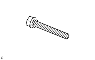
(a) Install the front disc brake cylinder mounting LH with the 2 bolts.
Torque:
106.8 N·m {1089 kgf·cm, 79 ft·lbf}
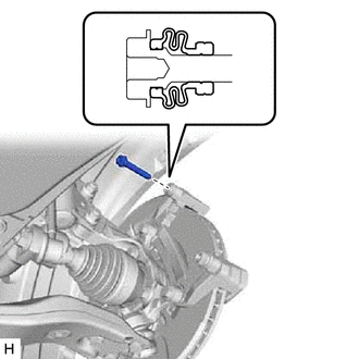
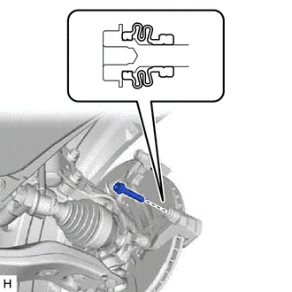
3. INSTALL FRONT DISC BRAKE BUSH DUST BOOT
(a) Apply a light coat of lithium soap base glycol grease to the entire circumference of 2 new front disc brake bush dust boots, and the entire inner circumference of both ends.
.png) | Lithium soap base glycol grease |
HINT:
Apply at least 0.3 g (0.01 oz.) of lithium soap base glycol grease to the front disc brake bush dust boot.
(b) Install the 2 front disc brake bush dust boots to the front disc brake cylinder mounting LH.
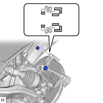
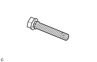
4. INSTALL FRONT DISC BRAKE CYLINDER SLIDE PIN
(a) Apply a light coat of lithium soap base glycol grease to the sliding part and the seal surface of the front disc brake cylinder slide pin.
| | Lithium soap base glycol grease |
| (b) Install the front disc brake cylinder slide pin to the front disc brake cylinder mounting LH. |
|
(c) Push the front disc brake cylinder slide pin into the front disc brake bush dust boot to align them.
5. INSTALL FRONT DISC BRAKE CYLINDER SLIDE BUSH
(a) Apply a light coat of lithium soap base glycol grease to the contact surface of the No. 2 disc brake cylinder slide pin where it contacts the front disc brake cylinder slide bush.
| | Lithium soap base glycol grease |
(b) Install a new front disc brake cylinder slide bush to the No. 2 disc brake cylinder slide pin.
6. INSTALL NO. 2 DISC BRAKE CYLINDER SLIDE PIN
(a) Apply a light coat of lithium soap base glycol grease to the sliding part and the seal surface of the No. 2 disc brake cylinder slide pin.
| | Lithium soap base glycol grease |
| (b) Install the No. 2 disc brake cylinder slide pin to the front disc brake cylinder mounting LH. |
|
(c) Push the No. 2 disc brake cylinder slide pin into the front disc brake bush dust boot to align them.
7. INSTALL FRONT NO. 1 DISC BRAKE PAD SUPPORT PLATE
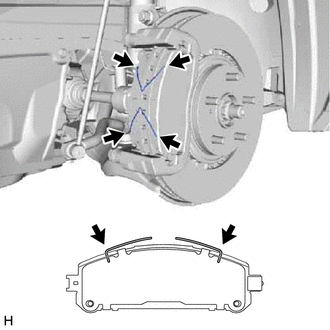
| (a) Install the 4 front disc brake pad support plates to the front disc brake cylinder mounting LH as shown in the illustration. NOTICE:
|
|
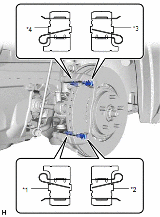
8. INSTALL FRONT NO. 2 DISC BRAKE PAD SUPPORT PLATE
9. INSTALL FRONT NO. 3 DISC BRAKE PAD SUPPORT PLATE
10. INSTALL FRONT NO. 4 DISC BRAKE PAD SUPPORT PLATE
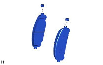
11. INSTALL NO. 1 PAD WEAR INDICATOR PLATE
| (a) Install the 2 new No. 1 pad wear indicator plates to the 2 front disc brake pads. NOTICE: Install the pad wear indicator plates in the correct positions and directions. |
|
12. INSTALL FRONT ANTI-SQUEAL SHIM KIT
(a) Apply disc brake grease to the inside of the 2 No. 1 anti-squeal shims as shown in the illustration.
 | Area for disc brake grease application |
NOTICE:
- When replacing worn pads, the No. 1 anti-squeal shims must be replaced together with the pads.
- Apply disc brake grease to the area that contacts the No. 1 anti-squeal shims.
- Disc brake grease can come out slightly from the area where the No. 1 anti-squeal shims are installed.
- Make sure that disc brake grease is not applied onto the lining surface.
| (b) Install the 2 No. 1 anti-squeal shims to the pads. |
|
13. INSTALL FRONT DISC BRAKE PAD
(a) Install the 2 front disc brake pads with the 2 No. 1 anti-squeal shims to the front disc brake cylinder mounting LH.
| (b) Install the 2 anti-squeal springs to the front disc brake pads. NOTICE:
|
|
14. INSTALL DISC BRAKE CYLINDER ASSEMBLY LH
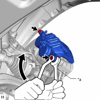
| (a) Hold the front disc brake cylinder slide pin and install the disc brake cylinder assembly LH to the disc brake cylinder mounting LH with 2 bolts. Torque: 34.3 N·m {350 kgf·cm, 25 ft·lbf} NOTICE:
|
|
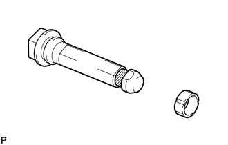
15. CONNECT FRONT FLEXIBLE HOSE
(a) Connect the front flexible hose to the disc brake cylinder assembly LH with a new gasket and a new union bolt.
Torque:
30.4 N·m {310 kgf·cm, 22 ft·lbf}
NOTICE:
Install the front flexible hose lock securely in the lock hole in the disc brake cylinder assembly LH.
16. CONNECT CABLE TO NEGATIVE AUXILIARY BATTERY TERMINAL
(a) Connect the cable to the negative (-) auxiliary battery terminal and tighten the nut.
Torque:
5.4 N·m {55 kgf·cm, 48 in·lbf}
(b) Perform the following procedure if air bleeding is not necessary.
(1) Connect the reservoir level switch connector.
(2) Clear the DTCs.
Click here .gif)
17. INITIALIZATION AFTER RECONECTING AUXILIARY BATTERY TERMINAL
Click here
HINT:
When disconnecting and reconnecting the auxiliary battery, there is an automatic learning function that completes learning when the respective system is used.
Click here
18. INSTALL DECK FLOOR BOX LH
Click here
19. INSTALL REAR DECK FLOOR BOX
Click here
20. INSTALL NO. 3 DECK BOARD SUB-ASSEMBLY
Click here
21. BLEED BRAKE LINE
Click here
22. INSTALL FRONT WHEEL
Click here
READ NEXT:
 Components
COMPONENTS ILLUSTRATION *1 DECK FLOOR BOX LH *2 NO. 3 DECK BOARD SUB-ASSEMBLY *3 REAR DECK FLOOR BOX *4 NEGATIVE AUXILIARY BATTERY TERMINAL N*m (kgf*cm, ft.*lbf): Specified
Removal
REMOVAL CAUTION / NOTICE / HINT HINT:
Use the same procedure for the RH and LH sides.
The following procedure is for the LH side.
NOTICE:
While the auxiliary battery is connected, even if t
SEE MORE:
Components
COMPONENTS ILLUSTRATION *A w/ Woofer *B w/o Woofer *1 BACK DOOR CENTER GARNISH *2 BACK DOOR LOCK COVER *3 BACK DOOR SIDE GARNISH LH *4 BACK DOOR SIDE GARNISH RH *5 BACK DOOR TRIM BASE *6 BACK DOOR TRIM BOARD ASSEMBLY *7 POWER BACK DOOR WARNING BUZZER *
Mirror Heater does not Operate with Rear Defogger Switch
DESCRIPTION When the rear window defogger switch (mirror heater switch) on the air conditioning control assembly is pressed, the operation signal is transmitted to the air conditioning amplifier assembly via LIN communication. When the air conditioning amplifier assembly receives the signal, it turn
