Lexus NX: Windshield Deicer does not Operate
DESCRIPTION
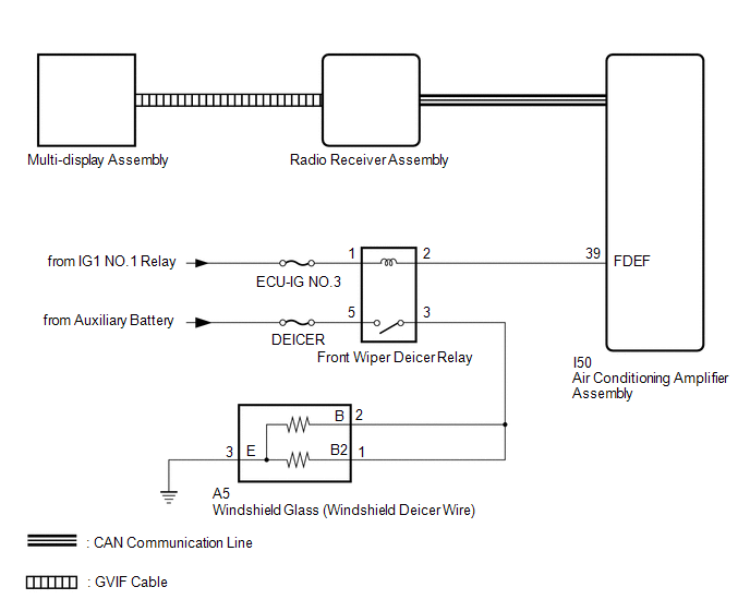
When the windshield deicer switch is operated, the operation signal is transmitted to the radio receiver assembly. The radio receiver assembly transmits the operation signal to the air conditioning amplifier assembly via the CAN communication line.
WIRING DIAGRAM
CAUTION / NOTICE / HINT
NOTICE:
- Inspect the fuses for circuits related to this system before performing the following procedure.
-
If the auxiliary battery voltage becomes low, windshield deicer operation is canceled to prioritize supplying power to the power steering system.
for Power Tilt and Power Telescopic Steering Column: Click here
.gif)
for Manual Tilt and Manual Telescopic Steering Column: Click here
-
Troubleshoot the windshield deicer system after confirming that the navigation system (w/ Navigation System) or audio and visual system (w/ Audio and Visual System) is functioning properly.
w/ Navigation System: Click here
w/ Audio and Visual System: Click here
PROCEDURE
| 1. | PERFORM ACTIVE TEST USING TECHSTREAM |
(a) Using the Techstream, perform the Active Test.
Click here
| Tester Display | Measurement Item | Control Range | Diagnostic Note |
|---|---|---|---|
| Deicer Relay (Front) | Windshield glass (windshield deicer wire) | OFF or ON | - |
| Tester Display |
|---|
| Deicer Relay (Front) |
OK:
The windshield deicer system operates normally.
| NG | .gif) | GO TO STEP 4 |
|
.gif)
| 2. | CHECK AIR CONDITIONING AMPLIFIER ASSEMBLY |
(a) Replace the air conditioning amplifier assembly with a new or normally functioning one.
Click here
(b) Check that the window deicer system operates normally.
OK:
The window deicer system operates normally.
| OK | | END (AIR CONDITIONING AMPLIFIER ASSEMBLY IS DEFECTIVE) |
|
| 3. | CHECK MULTI-DISPLAY ASSEMBLY |
(a) Replace the multi-display assembly with a new or normally functioning one.
Click here
(b) Check that the window deicer system operates normally.
OK:
The window deicer system operates normally.
| OK | | END (MULTI-DISPLAY ASSEMBLY IS DEFECTIVE) |
| NG | | REPLACE RADIO RECEIVER ASSEMBLY |
| 4. | CHECK HARNESS AND CONNECTOR (WINDSHIELD GLASS - BATTERY) |
| (a) Disconnect the windshield glass (windshield deicer wire) connector. |
|
(b) Measure the voltage according to the value(s) in the table below.
Standard Voltage:
| Tester Connection | Switch Condition | Specified Condition |
|---|---|---|
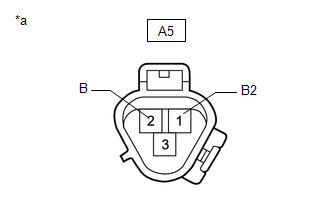
| A5-2 (B) - Body ground | Power switch on (IG), windshield deicer switch on | 11 to 14 V |
| A5-1 (B2) - Body ground |
| NG | | GO TO STEP 6 |
|
| 5. | CHECK HARNESS AND CONNECTOR (WINDSHIELD GLASS - BODY GROUND) |
| (a) Disconnect the windshield glass (windshield deicer wire) connector. |
|
(b) Measure the resistance according to the value(s) in the table below.
Standard Resistance:
| Tester Connection | Condition | Specified Condition |
|---|---|---|
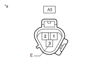
| A5-3 (E) - Body ground | Always | Below 1 Ω |
| OK | | REPLACE WINDSHIELD GLASS (WINDSHIELD DEICER WIRE) |
| NG | | REPAIR OR REPLACE HARNESS OR CONNECTOR |
| 6. | INSPECT FRONT WIPER DEICER RELAY |
(a) Remove the front wiper deicer relay from the No. 2 engine room relay block.
(b) Inspect the front wiper deicer relay.
Click here
| NG | | REPLACE FRONT WIPER DEICER RELAY |
|
| 7. | CHECK HARNESS AND CONNECTOR (FRONT WIPER DEICER RELAY - BATTERY) |
| (a) Remove the front wiper deicer relay from the No. 2 engine room relay block. |
|
(b) Measure the voltage according to the value(s) in the table below.
Standard Voltage:
| Tester Connection | Switch Condition | Specified Condition |
|---|---|---|
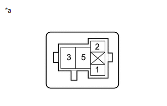
| Front wiper deicer relay terminal 5 - Body ground | Power switch off | 11 to 14 V |
| Front wiper deicer relay terminal 1 - Body ground | Power switch on (IG) | 11 to 14 V |
| NG | | REPAIR OR REPLACE HARNESS OR CONNECTOR |
|
| 8. | CHECK HARNESS AND CONNECTOR (FRONT WIPER DEICER RELAY - AIR CONDITIONING AMPLIFIER ASSEMBLY AND WINDSHIELD GLASS) |
(a) Disconnect the A5 windshield glass (windshield deicer wire) connector.
(b) Disconnect the I50 air conditioning amplifier assembly connector.
(c) Remove the front wiper deicer relay from the No. 2 engine room relay block.
(d) Measure the resistance according to the value(s) in the table below.
Standard Resistance:
| Tester Connection | Condition | Specified Condition |
|---|---|---|
| Front wiper deicer relay terminal 3 - A5-2 (B) | Always | Below 1 Ω |
| Front wiper deicer relay terminal 3 - A5-1 (B2) | Always | Below 1 Ω |
| Front wiper deicer relay terminal 2 - I50-39 (FDEF) | Always | Below 1 Ω |
| Front wiper deicer relay terminal 3 or A5-2 (B) - Body ground | Always | 10 kΩ or higher |
| Front wiper deicer relay terminal 3 or A5-1 (B2) - Body ground | Always | 10 kΩ or higher |
| Front wiper deicer relay terminal 2 or I50-39 (FDEF) - Body ground | Always | 10 kΩ or higher |
| OK | | REPLACE AIR CONDITIONING AMPLIFIER ASSEMBLY |
| NG | | REPAIR OR REPLACE HARNESS OR CONNECTOR |
READ NEXT:
 Components
COMPONENTS ILLUSTRATION *1 COWL TOP VENTILATOR LOUVER SUB-ASSEMBLY *2 FRONT FENDER TO COWL SIDE SEAL LH *3 FRONT FENDER TO COWL SIDE SEAL RH *4 FRONT WIPER ARM HEAD CAP *5 FR
Removal
REMOVAL CAUTION / NOTICE / HINT NOTICE: When replacing the windshield glass of a vehicle equipped with a forward recognition camera, make sure to use a Lexus genuine part. If a non-Lexus genuine part
SEE MORE:
System Description
SYSTEM DESCRIPTION AUTOMATIC HIGH BEAM SYSTEM (a) General The automatic high beam system enhances the illumination of the area in front of the vehicle to improve visibility for the driver. It works by detecting light from the front of the vehicle, using the forward recognition camera, and turns the
Motor Rotation Angle Sensor (C1528)
DESCRIPTION The motor rotation angle sensor detects the motor rotation angle and sends this information to the power steering ECU assembly. DTC No. Detection Item DTC Detection Condition Trouble Area Warning Indicate Return-to-normal Condition C1528 Motor Rotation Angle Sensor M
