Lexus NX: Remote Engine Starter does not Operate
WIRING DIAGRAM
CAUTION / NOTICE / HINT
NOTICE:
Before replacing the certification ECU (smart key ECU assembly), refer to smart access system with push-button start (for Entry Function) Precaution.
Click here .gif)
PROCEDURE
| 1. | CHECK SMART ACCESS SYSTEM WITH PUSH-BUTTON START (for Start Function) |
(a) Check that the power source mode can be changed to on (READY) by pressing the power switch.
| Result | Proceed to |
|---|---|
| Power source mode can be changed to on (READY). | A |
| Power source mode cannot be changed to on (READY). | B |
| B | .gif) | GO TO SMART ACCESS SYSTEM WITH PUSH-BUTTON START (for Start Function) |
|
.gif)
| 2. | REGISTRATION |
HINT:
If registration is not performed after replacing any of the following parts, the remote engine start and stop will not be available.- Certification ECU (smart key ECU assembly)
- DCM (telematics transceiver)
(a) Perform remote engine start and stop registration.
Click here
(b) Check if the problem symptom recurs.
| Result | Proceed to |
|---|---|
| System does not return to normal. | A |
| System returns to normal. | B |
| B | | END (COMMUNICATION ID REGISTRATION WAS NOT PERFORMED) |
|
| 3. | CHECK DTC OUTPUT |
(a) Clear the DTCs.
Click here
(b) Check for DTCs.
Click here
| Result | Proceed to |
|---|---|
| DTCs are not output. | A |
| DTC B2285 is output. | B |
| B | | GO TO DTC (B2285) |
|
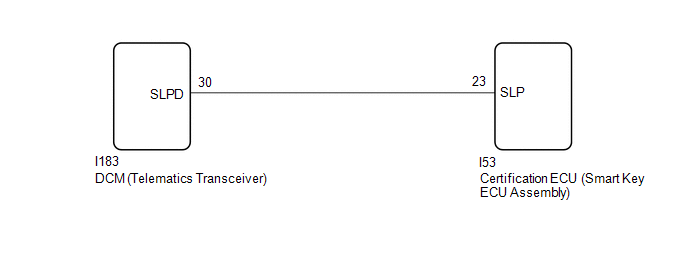
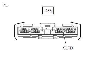
| 4. | CHECK DCM (TELEMATICS TRANSCEIVER) |
| (a) Disconnect the DCM (telematics transceiver) connector. |
|
(b) Measure the voltage according to the value(s) in the table below.
Standard Voltage:
| Tester Connection | Condition | Specified Condition |
|---|---|---|
| I183-30 (SLPD) - Body ground | Steering locked | 11 to 14 V |
| Steering unlocked | 1.5 V or less |
HINT:
The steering locks when any door is opened with the shift lever in P and the power switch off. The steering unlocks when the power switch is turned on (IG).
| OK | | REPLACE DCM (TELEMATICS TRANSCEIVER) |
|
| 5. | CHECK HARNESS AND CONNECTOR (DCM [TELEMATICS TRANSCEIVER] - CERTIFICATION ECU [SMART KEY ECU ASSEMBLY]) |
(a) Disconnect the I183 DCM (telematics transceiver) connector.
(b) Disconnect the I53 certification ECU (smart key ECU assembly) connector.
(c) Measure the resistance according to the value(s) in the table below.
Standard Resistance:
| Tester Connection | Condition | Specified Condition |
|---|---|---|
| I183-30 (SLPD) - I53-23 (SLP) | Always | Below 1 Ω |
| OK | | REPLACE CERTIFICATION ECU (SMART KEY ECU ASSEMBLY) |
| NG | | REPAIR OR REPLACE HARNESS OR CONNECTOR |
READ NEXT:
 Remote Service Malfunction
PROCEDURE 1. CHECK CAN COMMUNICATION SYSTEM (a) Connect the Techstream to the DLC3. (b) Turn the power switch on (IG). (c) Turn the Techstream on. (d) Enter the following menus: Bus Check. Cl
Warning Notification Function Malfunction
CAUTION / NOTICE / HINT NOTICE: When replacing the radio receiver assembly, always replace it with a new one. If a radio receiver assembly which was installed to another vehicle is used, the following
SEE MORE:
Customize Parameters
CUSTOMIZE PARAMETERS CUSTOMIZE INTELLIGENT CLEARANCE SONAR SYSTEM (a) Customizing with the Techstream. NOTICE:
When the customer requests a change in a function, first make sure that the function can be customized.
Be sure to make a note of the current settings before customizing.
When troubl
Dtc Check / Clear
DTC CHECK / CLEAR CHECK DTC (a) Connect the Techstream to the DLC3. (b) Turn the power switch on (IG). (c) Turn the Techstream on. (d) Enter the following menus: Body Electrical / Telematics / Trouble Codes. Body Electrical > Telematics > Trouble Codes (e) Check for DTCs. Click here CLEAR DT
