Lexus NX: Removal
REMOVAL
CAUTION / NOTICE / HINT
HINT:
- Use the same procedure for the RH and LH sides.
- The procedure listed below is for the LH side.
PROCEDURE
1. PRECAUTION
NOTICE:
After turning the power switch off, waiting time may be required before disconnecting the cable from the negative (-) auxiliary battery terminal.
Click here .gif)
2. REMOVE NO. 3 DECK BOARD SUB-ASSEMBLY
Click here
3. REMOVE REAR DECK FLOOR BOX
Click here
4. REMOVE DECK FLOOR BOX LH
Click here
5. DISCONNECT CABLE FROM NEGATIVE AUXILIARY BATTERY TERMINAL
CAUTION:
Wait at least 90 seconds after disconnecting the cable from the negative (-) battery terminal to disable the SRS system.
6. REMOVE REAR DOOR TRIM COVER LH
Click here
7. REMOVE REAR DOOR INSIDE HANDLE BEZEL PLUG LH
Click here
8. REMOVE REAR POWER WINDOW REGULATOR SWITCH ASSEMBLY WITH REAR DOOR ARMREST BASE PANEL
Click here
9. REMOVE REAR DOOR TRIM BOARD SUB-ASSEMBLY LH
Click here
10. REMOVE REAR DOOR INNER GLASS WEATHERSTRIP LH
Click here
11. REMOVE REAR DOOR ARMREST SET BRACKET LH
Click here
12. REMOVE REAR DOOR SERVICE HOLE COVER LH
Click here
13. REMOVE REAR DOOR GLASS RUN LH
Click here
14. REMOVE REAR DOOR REAR LOWER WINDOW FRAME SUB-ASSEMBLY LH
Click here
15. REMOVE REAR DOOR REAR GUIDE SEAL LH
Click here
16. REMOVE REAR DOOR GLASS SUB-ASSEMBLY LH
Click here
17. REMOVE REAR DOOR LOCK ASSEMBLY LH
(a) Disconnect the connector.
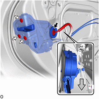
| *1 | Release Plate |
.png) | Downward |
(b) Using a T30 "TORX" socket wrench, remove the 3 screws.
(c) Slide the rear door lock assembly LH downward, and pull the release plate out of the rear door outside handle frame sub-assembly LH.
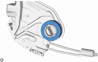
18. REMOVE DOOR LOCK WIRING HARNESS SEAL
| (a) Remove the door lock wiring harness seal from the rear door lock assembly LH. |
|
19. REMOVE REAR DOOR LOCK COVER SUB-ASSEMBLY LH
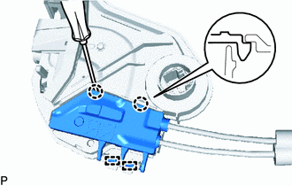
(a) Detach the 2 claws.
(b) Using a screwdriver, detach the 2 guides and remove the rear door lock cover sub-assembly LH from the rear door lock assembly LH.
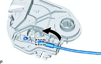
20. REMOVE REAR DOOR LOCK REMOTE CONTROL CABLE ASSEMBLY LH
| (a) Detach the clamp and remove the rear door lock remote control cable assembly LH from the rear door lock assembly LH. |
|
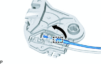
21. REMOVE REAR DOOR INSIDE LOCKING CABLE ASSEMBLY LH
| (a) Detach the clamp and remove the rear door inside locking cable assembly LH from the rear door lock assembly LH. |
|
READ NEXT:
 Inspection
INSPECTION PROCEDURE 1. INSPECT REAR DOOR LOCK ASSEMBLY LH (a) Check the door lock motor operation. (1) Apply auxiliary battery voltage to the motor connector and check the operation of the door lo
Installation
INSTALLATION CAUTION / NOTICE / HINT HINT:
Use the same procedure for the RH and LH sides.
The procedure listed below is for the LH side.
A bolt without a torque specification is shown in the s
Transmitter Battery
ReplacementREPLACEMENT PROCEDURE 1. REMOVE TRANSMITTER BATTERY (a) Push the release hook knob and extract the mechanical key. (b) Using a screwdriver with its tip wrapped in protect
SEE MORE:
Front Camera Response Malfunction (C2A6D)
DESCRIPTION During self diagnosis of the parking assist ECU, the parking assist ECU sends display mode ID signals to the front television camera assembly. This DTC is stored when the output of the front television camera assembly does not match the expected output. DTC No. Detection Item DTC
Replacement
REPLACEMENT PROCEDURE 1. REPLACE RING PIN NOTICE: It is not necessary to remove the ring pin unless it is being replaced. (a) Remove the 12 ring pins. (b) Using a plastic-faced hammer, install 12 new ring pins. *a Upper Side *b Lower Side *c 15 mm (0.591 in.) *d 14 mm (0.551 in.)
