Lexus NX: Replacement
REPLACEMENT
PROCEDURE
1. REPLACE RING PIN
NOTICE:
It is not necessary to remove the ring pin unless it is being replaced.
(a) Remove the 12 ring pins.
(b) Using a plastic-faced hammer, install 12 new ring pins.
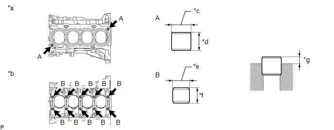
| *a | Upper Side | *b | Lower Side |
| *c | 15 mm (0.591 in.) | *d | 14 mm (0.551 in.) |
| *e | 13 mm (0.512 in.) | *f | 12 mm (0.472 in.) |
| *g | Protrusion Height | - | - |
Standard Protrusion Height:
| Item | Specified Condition |
|---|---|
| A | 5.0 to 7.0 mm (0.197 to 0.276 in.) |
| B | 4.0 to 7.0 mm (0.157 to 0.276 in.) |
2. REPLACE STRAIGHT PIN
NOTICE:
It is not necessary to remove the straight pin unless it is being replaced.
(a) Remove the 14 straight pins.
(b) Using a plastic-faced hammer, install 14 new straight pins.
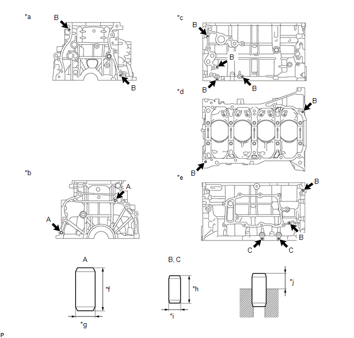
| *a | Front Side | *b | Rear Side |
| *c | LH Side | *d | Lower Side |
| *e | RH Side | *f | 22 mm (0.866 in.) |
| *g | 10 mm (0.394 in.) | *h | 14 mm (0.551 in.) |
| *i | 6 mm (0.236 in.) | *j | Protrusion Height |
Standard Protrusion Height:
| Item | Specified Condition |
|---|---|
| A | 11.0 to 13.0 mm (0.433 to 0.512 in.) |
| B | 5.0 to 7.0 mm (0.197 to 0.276 in.) |
| C | 4.0 to 6.0 mm (0.157 to 0.236 in.) |
READ NEXT:
 Reassembly
REASSEMBLY CAUTION / NOTICE / HINT HINT: Perform "Inspection After Repairs" after replacing the piston or piston ring. Click here PROCEDURE 1. INSTALL STUD BOLT NOTICE: If a stud bolt is deformed or
Precaution
PRECAUTION HINT:
Any digits beyond the 0.01 mm (1/1000 in.) place for standard, minimum and maximum values should be used as a reference only.
When both standard and maximum or minimum values are
SEE MORE:
High Voltage Power Resource (P3004-800,P3004-801)
DTC SUMMARY MALFUNCTION DESCRIPTION The hybrid vehicle control ECU monitors the high-voltage wiring between the HV battery and inverter with converter assembly and detects a short circuit malfunction or high-voltage system operation malfunction. The cause of this malfunction may be one of the follow
Power Steering Warning Light Circuit
DESCRIPTION The power steering ECU is connected to the combination meter via CAN communication. If any of the following conditions are detected, the power steering warning light remains on.
The circuit that supplies power source voltage to the power steering ECU assembly (terminal IG) is open.
