Lexus NX: Removal
REMOVAL
PROCEDURE
1. REMOVE DECK BOARD ASSEMBLY
Click here .gif)
2. REMOVE NO. 3 DECK BOARD SUB-ASSEMBLY
Click here
3. REMOVE REAR DECK FLOOR BOX
Click here
4. REMOVE DECK FLOOR BOX LH
Click here
5. PRECAUTION
CAUTION:
Be sure to read Precaution thoroughly before serving.
Click here
NOTICE:
After turning the power switch off, there may be a waiting time before disconnecting the negative (-) auxiliary battery terminal.
Click here
6. DISCONNECT CABLE FROM NEGATIVE AUXILIARY BATTERY TERMINAL
CAUTION:
- Wait at least 90 seconds after disconnecting the cable from the negative (-) auxiliary battery terminal to disable the SRS system.
- If the airbag deploys for any reason, it may cause a serious accident.
7. REMOVE DCM (TELEMATICS TRANSCEIVER)
Click here
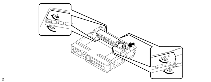
8. REMOVE TRANSCEIVER COVER
| (a) Detach the 2 claws and 2 guides and remove the transceiver cover as shown in the illustration. |
|
9. REMOVE MOBILEPHONE BATTERY
CAUTION:
- Do not reuse dropped or damaged parts.
- Wear gloves when contacting parts that have been dropped from a height of 1 m or higher.
- There may be an internal short or the temperature may increase to 100°C or higher due to the shock from being dropped.
- If an internal short has occurred, gas may be discharged. Therefore, if there is even a small amount of heat, maintain a distance of 3 m or more from the vehicle and wait for 1 minute or longer.
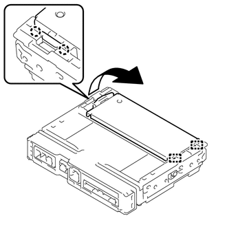
(a) Disconnect the connector and remove the mobilephone battery as shown in the illustration.
READ NEXT:
 Installation
INSTALLATION PROCEDURE 1. INSTALL MOBILEPHONE BATTERY CAUTION:
Do not reuse dropped or damaged parts.
Wear gloves when contacting parts that have been dropped from a height of 1 m or higher.
Th
Precaution
PRECAUTION WHEN DISCONNECTING AUXILIARY BATTERY CABLE NOTICE:
After turning the power switch off, waiting time may be required before disconnecting the cable from the negative (-) auxiliary battery
SEE MORE:
Components
COMPONENTS ILLUSTRATION *1 FRONT CENTER FLOOR COVER LH *2 NO. 1 ENGINE UNDER COVER ASSEMBLY *3 REAR ENGINE UNDER COVER LH *4 REAR ENGINE UNDER COVER RH ILLUSTRATION *1 FRONT CROSSMEMBER SUB-ASSEMBLY *2 FRONT SUSPENSION MEMBER REAR BRACE LH *3 FRONT SUSPENSION M
Parts Location
PARTS LOCATION ILLUSTRATION *A w/ Panoramic View Monitor System *B w/ Parking Assist Monitor System *1 FRONT CORNER ULTRASONIC SENSOR (FR SENSOR) *2 FRONT CENTER ULTRASONIC SENSOR (FRC SENSOR) *3 FRONT CENTER ULTRASONIC SENSOR (FLC SENSOR) *4 FRONT CORNER ULTRASONIC SEN
