Lexus NX: Removal
REMOVAL
CAUTION / NOTICE / HINT
HINT:
- Use the same procedure for the RH and LH sides.
- The procedure listed below is for the LH side.
PROCEDURE
1. REMOVE NO. 3 DECK BOARD SUB-ASSEMBLY
Click here .gif)
2. REMOVE REAR DECK FLOOR BOX
Click here
3. REMOVE DECK FLOOR BOX LH
Click here
4. PRECAUTION
CAUTION:
Be sure to read Precaution thoroughly before servicing.
Click here
NOTICE:
After the power switch is turned off, there may be a waiting time before disconnecting the negative (-) auxiliary battery terminal.
Click here
5. DISCONNECT CABLE FROM NEGATIVE AUXILIARY BATTERY TERMINAL
CAUTION:
Wait at least 90 seconds after disconnecting the cable from the negative (-) auxiliary battery terminal to disable the SRS system.
(a) Loosen the nut and disconnect the cable from the negative (-) auxiliary battery terminal.
6. REMOVE REAR SEAT ASSEMBLY (for Manual Seat)
HINT:
Perform the linked removal procedures until the No. 1 seat leg assembly step.
Click here
7. REMOVE REAR SEAT ASSEMBLY (for Power Seat)
HINT:
Perform the linked removal procedures until the No. 1 seat leg assembly step.
Click here
8. REMOVE SPARE TIRE
Click here
9. REMOVE REAR FLOOR FINISH PLATE
Click here
10. REMOVE REAR DOOR OPENING TRIM WEATHERSTRIP LH
Click here
11. REMOVE UPPER DECK TRIM SIDE BOARD LH
Click here
12. REMOVE ROPE HOOK ASSEMBLY
Click here
13. REMOVE LUGGAGE HOLD BELT STRIKER ASSEMBLY
Click here
14. REMOVE NO. 1 LUGGAGE COMPARTMENT TRIM HOOK
Click here
15. REMOVE DECK TRIM SIDE PANEL ASSEMBLY LH
Click here
16. REMOVE SIDE AIRBAG SENSOR ASSEMBLY LH
(a) Check that the power switch is off.
(b) Check that the cable is disconnected from the negative (-) auxiliary battery terminal.
CAUTION:
Wait at least 90 seconds after disconnecting the cable from the negative (-) auxiliary battery terminal to disable the SRS system.
(c) Disconnect the airbag connector.
NOTICE:
When disconnecting any airbag connector, take care not to damage the airbag wire harness.
(1) Push down the housing lock and slide the CPA. (At this time, the connector cannot be disconnected yet.)
(2) Push the housing lock again and disconnect the airbag connector.
NOTICE:
Do not push down the upper part of the CPA shown in the illustration when disconnecting the airbag connector.
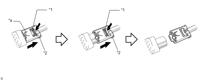
| *1 | Housing Lock | *2 | CPA |
| *a | CPA Upper Part | - | - |
| (d) Remove the nut. NOTICE: Loosen the nut while holding the side airbag sensor assembly LH because the side airbag sensor assembly LH guide is easily damaged. |
|
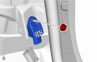
(e) Detach the guide and remove the side airbag sensor assembly LH.
READ NEXT:
 Installation
INSTALLATION CAUTION / NOTICE / HINT HINT:
Use the same procedure for the RH and LH sides.
The procedure listed below is for the LH side.
PROCEDURE 1. INSTALL SIDE AIRBAG SENSOR ASSEMBLY LH (a
Components
COMPONENTS ILLUSTRATION *1 DECK FLOOR BOX LH *2 NO. 3 DECK BOARD SUB-ASSEMBLY *3 REAR DECK FLOOR BOX *4 AUXILIARY BATTERY NEGATIVE TERMINAL N*m (kgf*cm, ft.*lbf): Specified
SEE MORE:
Cooling System
On-vehicle InspectionON-VEHICLE INSPECTION PROCEDURE 1. INSPECT FOR COOLANT LEAK CAUTION: To avoid the danger of being burned, do not remove the radiator reservoir cap while the engine assembly and radiator assembly are still hot. Thermal expansion will cause hot engine coolant and steam to blow ou
Headlight ECU Communication Stop Mode
DESCRIPTION Detection Item Symptom Trouble Area Headlight ECU Communication Stop Mode Any of the following conditions are met:
Communication stop for "Headlight swivel (AFS)" is indicated on the "Communication Bus Check" screen of the Techstream.
Click here
Communication system
