Lexus NX: Removal
REMOVAL
PROCEDURE
1. REMOVE DECK BOARD ASSEMBLY
Click here .gif)
2. REMOVE NO. 3 DECK BOARD SUB-ASSEMBLY
Click here
3. REMOVE REAR DECK FLOOR BOX
Click here
4. REMOVE DECK FLOOR BOX LH
Click here
5. PRECAUTION
CAUTION:
Be sure to read Precaution thoroughly before serving.
Click here
NOTICE:
After turning the power switch off, there may be a waiting time before disconnecting the negative (-) auxiliary battery terminal.
Click here
6. DISCONNECT CABLE FROM NEGATIVE AUXILIARY BATTERY TERMINAL
CAUTION:
- Wait at least 90 seconds after disconnecting the cable from the negative (-) auxiliary battery terminal to disable the SRS system.
- If the airbag deploys for any reason. it may cause a serious accident.
7. REMOVE INSTRUMENT PANEL FINISH PLATE
Click here
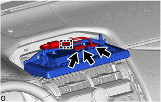
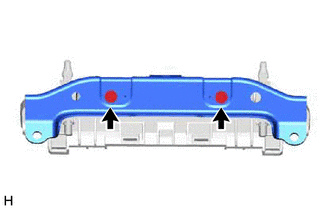
8. REMOVE MULTI-DISPLAY ASSEMBLY WITH BRACKET
(a) for 8 inch:
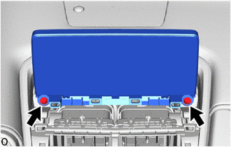
(1) Remove the 2 bolts.
| (2) Move the multi-display assembly with bracket as indicated by the arrow shown in the illustration to detach the 2 clips. |
|

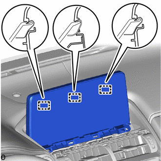
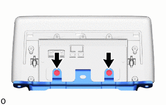
| (3) Detach the 3 guides. |
|
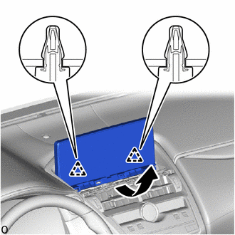
| (4) Disconnect the 3 connector. |
|

(5) Detach the clamp and remove the multi-display assembly with bracket.
(b) for 10.3 inch:
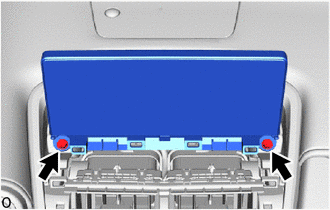
(1) Remove the 2 bolts.
| (2) Move the multi-display assembly with bracket as indicated by the arrow shown in the illustration to detach the 2 clips. |
|
| (3) Detach the 3 guides. |
|

| (4) Disconnect the 3 connector. |
|
(5) Detach the clamp and remove the multi-display assembly with bracket.
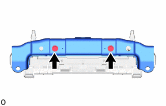
9. REMOVE MULTI-DISPLAY CONTROLLER BRACKET A
(a) for 8 inch:
| (1) Remove the 2 screws. |
|
| (2) Remove the 2 screws and multi-display controller bracket A. |
|
(b) for 10.3 inch:
| (1) Remove the 2 screws. |
|
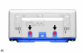
| (2) Remove the 2 screws and multi-display controller bracket A. |
|
10. REMOVE MULTI-DISPLAY ASSEMBLY
READ NEXT:
 Installation
INSTALLATION PROCEDURE 1. INSTALL MULTI-DISPLAY ASSEMBLY 2. INSTALL MULTI-DISPLAY CONTROLLER BRACKET A (a) for 8 inch: (1) Temporarily install the multi-display controller bracket A with the 2 scre
Components
COMPONENTS ILLUSTRATION *1 NAVIGATION ANTENNA ASSEMBLY WITH BRACKET *2 NO. 1 HEATER TO REGISTER DUCT SUB-ASSEMBLY *3 UPPER INSTRUMENT PANEL SUB-ASSEMBLY - - ILLUSTRATION *1
SEE MORE:
Reassembly
REASSEMBLY PROCEDURE 1. INSTALL REAR BUMPER PAD HINT:
When installing the rear bumper pad, heat the rear bumper cover and rear bumper pad using a heat light.
Use the same procedure described for the other side.
Standard: Item Temperature Rear Bumper Cover 20 to 30°C (68 to 86°F
System Description
SYSTEM DESCRIPTION
The power steering system generates torque through the operation of the motor and the reduction gear installed on the column shaft in order to assist steering effort.
The power steering ECU assembly determines the direction and amount of assist power in accordance with vehicl
