Lexus NX: Reassembly
REASSEMBLY
PROCEDURE
1. INSTALL REAR BUMPER PAD
HINT:
- When installing the rear bumper pad, heat the rear bumper cover and rear bumper pad using a heat light.
- Use the same procedure described for the other side.
Standard:
| Item | Temperature |
|---|---|
| Rear Bumper Cover | 20 to 30°C (68 to 86°F) |
| Rear Bumper Pad | 20 to 30°C (68 to 86°F) |
NOTICE:
Do not heat the rear bumper cover and rear bumper pad excessively.
(a) Clean the rear bumper cover surface.
(1) Using a heat light, heat the rear bumper cover surface.
(2) Remove the double-sided tape from the rear bumper cover.
(3) Wipe off any tape adhesive residue with cleaner.
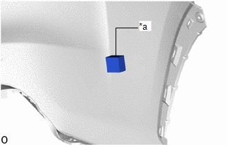
| (b) Install a new rear bumper pad. (1) Using a heat light, heat the rear bumper cover and rear bumper pad. (2) Remove the peeling paper from the face of the rear bumper pad. HINT: After removing the peeling paper, keep the exposed adhesive free from foreign matter. (3) Align the rear bumper pad with the scribed line on the rear bumper cover and install it as shown in the illustration. HINT: Press the rear bumper pad firmly to install it. |
|
2. INSTALL NO. 1 MOULDING TAPE
HINT:
- When installing the No. 1 moulding tape, heat the rear bumper cover and No. 1 moulding tape using a heat light.
- Use the same procedure described for the other side.
Standard:
| Item | Temperature |
|---|---|
| Rear Bumper Cover | 20 to 30°C (68 to 86°F) |
| No. 1 Moulding Tape | 20 to 30°C (68 to 86°F) |
NOTICE:
Do not heat the rear bumper cover and No. 1 moulding tape excessively.
(a) Clean the rear bumper cover surface.
(1) Using a heat light, heat the rear bumper cover surface.
(2) Remove the double-sided tape from the rear bumper cover.
(3) Wipe off any tape adhesive residue with cleaner.
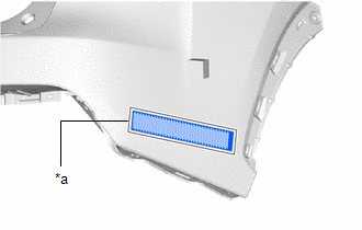
| (b) Install a new No. 1 moulding tape. (1) Using a heat light, heat the rear bumper cover and No. 1 moulding tape. (2) Remove the peeling paper from the face of the No. 1 moulding tape. HINT: After removing the peeling paper, keep the exposed adhesive free from foreign matter. (3) Align the No. 1 moulding tape with the scribed line on the rear bumper cover and install it as shown in the illustration. HINT: Press the No. 1 moulding tape firmly to install it. |
|
3. INSTALL REAR BUMPER LOWER RETAINER LH
| (a) Attach the 2 guides and install the rear bumper lower retainer LH. |
|
.png)
(b) Install the 3 screws.
4. INSTALL REAR BUMPER LOWER RETAINER RH
| (a) Attach the 2 guides and install the rear bumper lower retainer RH. |
|
.png)
(b) Install the 2 screws.
5. INSTALL REAR BUMPER LOWER SIDE RETAINER LH
| (a) Attach the guide and 4 claws and install the rear bumper lower side retainer LH. |
|
.png)
(b) Install the 2 screws.
6. INSTALL REAR BUMPER LOWER SIDE RETAINER RH
HINT:
Use the same procedure described for the LH side.
7. INSTALL REAR BUMPER CORNER EXTENSION RH
| (a) Install the rear bumper corner extension RH with the 2 screws. |
|
.png)
8. INSTALL REFLEX REFLECTOR ASSEMBLY LH
| (a) Attach the guide to install the reflex reflector assembly LH. |
|
.png)
(b) Install the screw.
9. INSTALL REFLEX REFLECTOR ASSEMBLY RH
HINT:
Use the same procedure as for the LH side.
10. INSTALL REAR BUMPER LOWER COVER
(a) Attach the 4 claws to install the rear bumper lower cover.
(b) Install the 8 outside moulding retainers in the figure direction.
(c) Install the 2 clips.
(d) Install the 4 screws.
.png)
11. INSTALL REAR CORNER ULTRASONIC SENSOR RETAINER (w/ Intuitive Parking Assist System)
Click here .gif)
12. INSTALL REAR CENTER ULTRASONIC SENSOR RETAINER (w/ Intuitive Parking Assist System)
Click here
13. INSTALL REAR CORNER ULTRASONIC SENSOR (w/ Intuitive Parking Assist System)
Click here
14. INSTALL REAR CENTER ULTRASONIC SENSOR (w/ Intuitive Parking Assist System)
Click here
15. INSTALL NO. 2 LUGGAGE ROOM WIRE
(a) w/ Intuitive Parking Assist System:
Connect the 4 connectors.
NOTICE:
Do not apply excessive loads to the retainer. Otherwise, it may peel off.
HINT:
Connect the connector while pressing the ultrasonic sensor with your hand.
(b) w/o Hands Free Power Back Door:
Attach the 6 clamps and install the No. 2 luggage room wire.
(c) w/ Hands Free Power Back Door:
Attach the 10 clamps and install the No. 2 luggage room wire.
.png)
| *A | w/ Hands Free Power Back Door | - | - |
16. INSTALL KICK DOOR CONTROL SENSOR (w/ Hands Free Power Back Door)
Click here
17. INSTALL KICK DOOR CONTROL BRACKET (w/ Hands Free Power Back Door)
Click here
READ NEXT:
 Installation
INSTALLATION PROCEDURE 1. INSTALL REAR BUMPER SIDE SUPPORT LH (a) Attach the 2 claws to install the rear bumper side support LH. (b) Attach the clip. (c) Install the screw. 2. INSTALL R
Components
COMPONENTS ILLUSTRATION *1 DECK FLOOR BOX LH *2 NO. 3 DECK BOARD SUB-ASSEMBLY *3 REAR DECK FLOOR BOX *4 NEGATIVE AUXILIARY BATTERY TERMINAL N*m (kgf*cm, ft.*lbf): Specified
SEE MORE:
Electric Parking Brake AUTO Indicator Light Circuit
WIRING DIAGRAM CAUTION / NOTICE / HINT NOTICE:
Inspect the fuses for circuits related to this system before performing the following inspection procedure.
Before disconnecting connectors or fuses, turn the power switch off and wait 20 seconds or more.
When replacing the parking brake ECU ass
Removal
REMOVAL PROCEDURE 1. REMOVE DECK BOARD ASSEMBLY (a) Remove the deck board assembly. 2. REMOVE NO. 3 DECK BOARD SUB-ASSEMBLY (a) Remove the No. 3 deck board sub-assembly. 3. REMOVE REAR DECK FLOOR BOX (a) Remove the rear deck floor box. 4. REMOVE DECK FLOO
