Lexus NX: Installation
INSTALLATION
PROCEDURE
1. INSTALL MULTI-DISPLAY ASSEMBLY
2. INSTALL MULTI-DISPLAY CONTROLLER BRACKET A
(a) for 8 inch:
| (1) Temporarily install the multi-display controller bracket A with the 2 screws. |
|
.png)
| (2) Install the 2 screws and tighten the 2 screws used to temporarily install the bracket. |
|
.png)
(b) for 10.3 inch:
| (1) Temporarily install the multi-display controller bracket A with the 2 screws. |
|
.png)
| (2) Install the 2 screws and tighten the 2 screws used to temporarily install the bracket. |
|
.png)
3. INSTALL MULTI-DISPLAY ASSEMBLY WITH BRACKET
(a) for 8 inch:
| (1) Connect the 3 connector and attach the clamp. |
|
.png)
| (2) Set the 3 guides. |
|
.png)
| (3) Move the multi-display assembly with bracket as shown in the illustration to attach the 2 clips. |
|
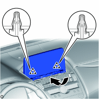
| (4) Install the 2 bolts and multi-display assembly with bracket. |
|
.png)
(b) for 10.3 inch:
| (1) Connect the 3 connector and attach the clamp. |
|
.png)
| (2) Set the 3 guides. |
|
.png)
| (3) Move the multi-display assembly with bracket as shown in the illustration to attach the 2 clips. |
|

| (4) Install the 2 bolts and multi-display assembly with bracket. |
|
.png)
4. INSTALL INSTRUMENT PANEL FINISH PLATE
Click here .gif)
5. CONNECT CABLE TO NEGATIVE AUXILIARY BATTERY TERMINAL
6. INITIALIZATION AFTER RECONNECTING AUXILIARY BATTERY TERMINAL
Click here
HINT:
When disconnecting and reconnecting the auxiliary battery, there is an automatic learning function that completes learning when the respective system is used.
Click here
7. CHECK SRS WARNING LIGHT
Click here
8. INSTALL DECK FLOOR BOX LH
Click here
9. INSTALL REAR DECK FLOOR BOX
Click here
10. INSTALL NO. 3 DECK BOARD SUB-ASSEMBLY
Click here
11. INSTALL DECK BOARD ASSEMBLY
Click here
READ NEXT:
 Components
COMPONENTS ILLUSTRATION *1 NAVIGATION ANTENNA ASSEMBLY WITH BRACKET *2 NO. 1 HEATER TO REGISTER DUCT SUB-ASSEMBLY *3 UPPER INSTRUMENT PANEL SUB-ASSEMBLY - - ILLUSTRATION *1
Removal
REMOVAL PROCEDURE 1. REMOVE UPPER INSTRUMENT PANEL SUB-ASSEMBLY Click here 2. REMOVE NO. 1 HEATER TO REGISTER DUCT SUB-ASSEMBLY Click here 3. REMOVE NAVIGATION ANTENNA ASSEMBLY WITH BRACKET (a
SEE MORE:
Components
COMPONENTS ILLUSTRATION *A for RH Side - - *1 REAR NO. 1 SEAT HEADREST SUPPORT ASSEMBLY *2 REAR SEAT CUSHION MOULDING RH *3 REAR SEAT CUSHION MOULDING RH *4 REAR SEAT HEADREST ASSEMBLY *5 REAR SEAT INNER WITH CENTER BELT ASSEMBLY RH *6 REAR SEATBACK BOARD CARP
Disassembly
DISASSEMBLY CAUTION / NOTICE / HINT HINT:
Use the same procedure for the RH and LH sides.
The procedure listed below is for the LH side.
PROCEDURE 1. REMOVE NO. 5 MOULDING TAPE (a) Remove the No. 5 moulding tape (double-sided tape). HINT: Do not pull on the No. 5 moulding tape (double-sided
