Lexus NX: Security Horn Circuit
DESCRIPTION
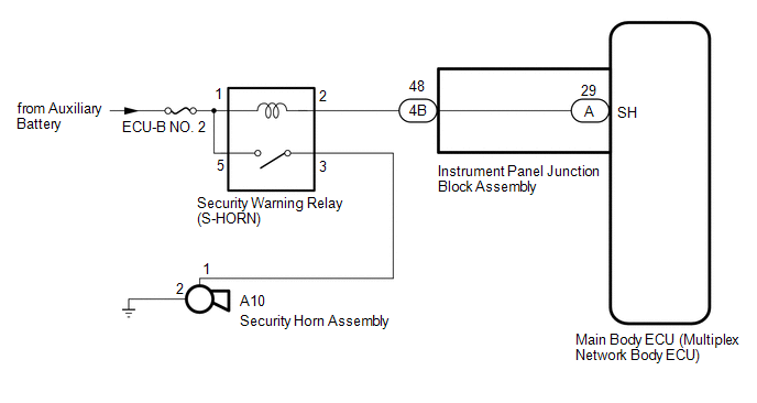
When the theft deterrent system is switched from the armed state to the alarm sounding state, the main body ECU (multiplex network body ECU) transmits a signal to cause the security horn to sound at intervals of 0.4 seconds.
WIRING DIAGRAM
CAUTION / NOTICE / HINT
NOTICE:
- Inspect the fuses for circuits related to this system before performing the following procedure.
-
If the main body ECU (multiplex network body ECU) is replaced, refer to Registration.
Click here
.gif)
PROCEDURE
| 1. | PERFORM ACTIVE TEST USING TECHSTREAM (SECURITY HORN) |
(a) Connect the Techstream to the DLC3.
(b) Turn the power switch on (IG).
(c) Turn the Techstream on.
(d) Enter the following menus: Body Electrical / Main Body / Active Test.
(e) According to the display on the Techstream, perform the Active Test.
Body Electrical > Main Body > Active Test| Tester Display | Measurement Item | Control Range | Diagnostic Note |
|---|---|---|---|
| Security Horn | Security horn assembly | ON or OFF | - |
| Tester Display |
|---|
| Security Horn |
OK:
The security horn assembly sounds and stops correctly when operated through the Techstream.
| OK | .gif) | REPLACE MAIN BODY ECU (MULTIPLEX NETWORK BODY ECU) |
|
.gif)
| 2. | INSPECT SECURITY HORN ASSEMBLY |
(a) Remove the security horn assembly.
Click here
(b) Inspect the security horn assembly.
Click here
| NG | | REPLACE SECURITY HORN ASSEMBLY |
|
| 3. | INSPECT SECURITY WARNING RELAY (S-HORN RELAY) |
| (a) Remove the security warning relay (S-HORN relay). |
|
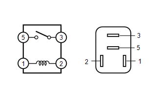
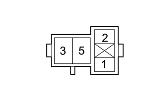
(b) Measure the resistance according to the value(s) in the table below
Standard Resistance:
| Tester Connection | Condition | Specified Condition |
|---|---|---|
| 3 - 5 | Battery voltage is applied between terminals 2 - 1 | Below 1 Ω |
| 3 - 5 | Battery voltage is not applied between terminals 2 - 1 | 10 kΩ or higher |
| NG | | REPLACE SECURITY WARNING RELAY (S-HORN RELAY) |
|
| 4. | CHECK HARNESS AND CONNECTOR (SECURITY WARNING RELAY [S-HORN RELAY] - MAIN BODY ECU [MULTIPLEX NETWORK BODY ECU]) |
(a) Remove the main body ECU (multiplex network body ECU).
Click here
(b) Connect the instrument panel junction block assembly connectors.
(c) Remove the security warning relay (S-HORN relay).
(d) Measure the resistance according to the value(s) in the table below.
Standard Resistance:
| Tester Connection | Condition | Specified Condition |
|---|---|---|
| 2 - A-29 (SH) | Always | Below 1 Ω |
| 2 - Body ground | Always | 10 kΩ or higher |
| A-29 (SH) - Body ground | Always | 10 kΩ or higher |
| NG | | GO TO STEP 7 |
|
| 5. | CHECK HARNESS AND CONNECTOR (BATTERY - SECURITY WARNING RELAY [S-HORN RELAY]) |
| (a) Remove the security warning relay (S-HORN relay). |
|
(b) Measure the voltage according to the value(s) in the table below.
Standard Voltage:
| Tester Connection | Switch Condition | Specified Condition |
|---|---|---|
| 1 - Body ground | Power switch off | 11 to 14 V |
| 5 - Body ground | Power switch off | 11 to 14 V |
| NG | | REPAIR OR REPLACE HARNESS OR CONNECTOR |
|
| 6. | CHECK HARNESS AND CONNECTOR (SECURITY WARNING RELAY [S-HORN RELAY] - SECURITY HORN ASSEMBLY AND BODY GROUND) |
(a) Remove the security warning relay (S-HORN relay).
(b) Disconnect the A10 security horn assembly connector.
(c) Measure the resistance according to the value(s) in the table below.
Standard Resistance:
| Tester Connection | Condition | Specified Condition |
|---|---|---|
| 3 - A10-1 | Always | Below 1 Ω |
| A10-2 - Body ground | Always | Below 1 Ω |
| 3 - Body ground | Always | 10 kΩ or higher |
| A10-1 - Body ground | Always | 10 kΩ or higher |
| OK | | REPLACE MAIN BODY ECU (MULTIPLEX NETWORK BODY ECU) |
| NG | | REPAIR OR REPLACE HARNESS OR CONNECTOR |
| 7. | CHECK HARNESS AND CONNECTOR (SECURITY HORN RELAY - INSTRUMENT PANEL JUNCTION BLOCK ASSEMBLY) |
(a) Disconnect the 4B instrument panel junction block assembly connector.
(b) Remove the security warning relay (S-HORN relay).
(c) Measure the resistance according to the value(s) in the table below.
Standard Resistance:
| Tester Connection | Condition | Specified Condition |
|---|---|---|
| 2 - 4B-48 | Always | Below 1 Ω |
| 2 - Body ground | Always | 10 kΩ or higher |
| 4B-48 - Body ground | Always | 10 kΩ or higher |
| OK | | REPLACE INSTRUMENT PANEL JUNCTION BLOCK ASSEMBLY |
| NG | | REPAIR OR REPLACE HARNESS OR CONNECTOR |
READ NEXT:
 Theft Warning Siren Circuit
DESCRIPTION The theft warning siren has an internal battery. If the vehicle auxiliary battery cable is disconnected or any of the communication lines are open, the theft warning siren detects this and
SEE MORE:
Removal
REMOVAL PROCEDURE 1. REMOVE HYBRID VEHICLE TRANSAXLE ASSEMBLY Click here 2. REMOVE TRANSMISSION INPUT DAMPER ASSEMBLY (a) Using SST, hold the crankshaft pulley assembly. SST: 09213-54015 SST: 09330-00021 HINT: Part number of installation bolt for SST (crankshaft pulley holding tool): 91551-806
Components
COMPONENTS ILLUSTRATION *A w/o Power Back Door *B w/ Power Back Door *1 BACK DOOR CENTER GARNISH *2 BACK DOOR FINISH COVER LH *3 BACK DOOR FINISH COVER RH *4 BACK DOOR SIDE GARNISH LH *5 BACK DOOR SIDE GARNISH RH *6 BACK DOOR TRIM BASE *7 BACK DOOR TRIM
