- Inverter Temp- (MG2)
- Inverter Temp- (MG1)
- Rear Inverter Temp
Lexus NX: Sensor of Rear Motor Inverter Temperature (P0AF3-676,P0AF6-675)
Lexus NX Service Manual / Engine & Hybrid System / 2ar-fxe (hybrid / Battery Control) / Hybrid Control System / Sensor of Rear Motor Inverter Temperature (P0AF3-676,P0AF6-675)
DTC SUMMARY
MALFUNCTION DESCRIPTION
These DTCs indicate the temperature sensor value for rear motor inverter is abnormal. The cause of this malfunction may be one of the following:
Internal inverter malfunction
- Inverter with converter assembly internal circuit malfunction
Hybrid cooling system malfunction
- Coolant circulation abnormal (frozen or leaking, etc.)
Inverter low-voltage circuit malfunction
- The connectors are not connected properly
DESCRIPTION
The MG ECU, which is built into the inverter with converter assembly, detects the temperature of the rear motor inverter using the temperature sensor built into the rear motor inverter. If necessary, the MG ECU will limit inverter output to help prevent the rear motor inverter from overheating. The hybrid vehicle control ECU also detects malfunctions in the sensor based on the temperature sensor values. The inverter with converter assembly detects malfunctions in the rear motor inverter temperature sensor and its wiring.
| DTC No. | Detection Item | DTC Detection Condition | Trouble Area | MIL | Warning Indicate |
|---|---|---|---|---|---|
| P0AF3-676 | Sensor of Rear Motor Inverter Temperature | Rear motor inverter temperature calculated by the hybrid vehicle control ECU is different from the actual temperature for 10 seconds or more, and the rear motor inverter temperature is excessively high. (1 trip detection logic) |
| Comes on | Master Warning Light: Comes on |
| P0AF6-675 | Drive Motor Inverter Temperature Sensor "B" Circuit Intermittent / Erratic | Sudden change in rear motor inverter temperature sensor output or hunting: Rear motor inverter temperature is high and either of the following conditions is met:
(1 trip detection logic) |
| Comes on | Master Warning Light: Comes on |
HINT:
*: If only DTC P0AF6-675 is output, a temperature sensor malfunction is more likely to be the cause than a sudden change in actual temperature.
Related Data List| DTC No. | ECU Data List |
|---|---|
| P0AF3-676 | |
| P0AF6-675 |
MONITOR DESCRIPTION
If the hybrid vehicle control ECU detects a malfunction of the rear motor inverter temperature sensor, it will illuminate the MIL and store a DTC.
MONITOR STRATEGY
| Related DTCs | P0AF3 (INF 676): Drive Motor Inverter Temperature Sensor "B" Circuit Range / Performance P0AF6 (INF 675): Drive Motor Inverter Temperature Sensor "B" Circuit Intermittent / Erratic |
| Required sensors/components | Rear motor inverter temperature sensor |
| Frequency of operation | Continuous |
| Duration | TMC's intellectual property |
| MIL operation | 1 driving cycle |
| Sequence of operation | None |
TYPICAL ENABLING CONDITIONS
| The monitor will run whenever the following DTCs are not stored | TMC's intellectual property |
| Other conditions belong to TMC's intellectual property | - |
TYPICAL MALFUNCTION THRESHOLDS
| TMC's intellectual property | - |
COMPONENT OPERATING RANGE
| Hybrid vehicle control ECU | DTC P0AF3 (INF 676) is not detected DTC P0AF6 (INF 675) is not detected |
CONFIRMATION DRIVING PATTERN
- Connect the Techstream to the DLC3.
- Turn the power switch on (IG) and turn the Techstream on.
- Clear the DTCs (even if no DTCs are stored, perform the clear DTC procedure).
- Turn the power switch off and wait for 30 seconds or more.
- Turn the power switch on (IG) and turn the Techstream on.
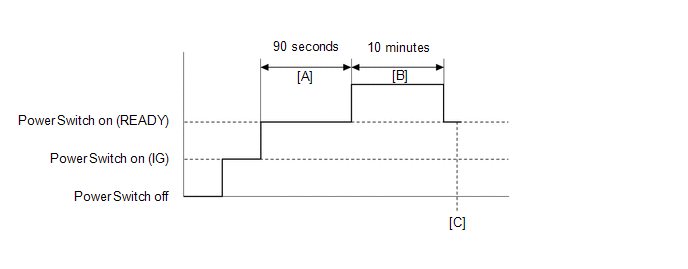
- Turn the power switch on (READY).
-
With the shift lever in P, wait for 90 seconds. [A]
HINT:
Check that there are no abnormalities (abnormal sounds, coolant leaks, DTC output, etc).
- Perform a road test according to the freeze frame data "Vehicle Spd" for approximately 10 minutes. [B]
- Enter the following menus: Powertrain / Hybrid Control / Trouble Codes. [C]
-
Read the current DTCs.
HINT:
- If a current DTC is output, the system is malfunctioning.
- If a current DTC is not output and want to confirm permanent DTC, perform the following procedure.
- Check that permanent DTCs are cleared. If no permanent DTC is output, the system is normal.
- If the permanent DTCs are not cleared, perform a universal trip, and then check for permanent DTCs again.
CAUTION / NOTICE / HINT
CAUTION:
- Before inspecting the high-voltage system or disconnecting the low voltage connector of the inverter with converter assembly, take safety precautions such as wearing insulated gloves and removing the service plug grip to prevent electrical shocks. After removing the service plug grip, put it in your pocket to prevent other technicians from accidentally reconnecting it while you are working on the high-voltage system.
-
After removing the service plug grip, wait for at least 10 minutes before touching any of the high-voltage connectors or terminals. After waiting for 10 minutes, check the voltage at the terminals in the inspection point in the inverter with converter assembly. The voltage should be 0 V before beginning work.
Click here
.gif)
HINT:
Waiting for at least 10 minutes is required to discharge the high-voltage capacitor inside the inverter with converter assembly.
NOTICE:
After turning the power switch off, waiting time may be required before disconnecting the cable from the negative (-) auxiliary battery terminal. Therefore, make sure to read the disconnecting the cable from the negative (-) auxiliary battery terminal notices before proceeding with work.
Click here
HINT:
After the repair, clear the DTCs and perform the following procedure to check that DTCs are not output.
- Turn the power switch on (READY) and wait for 90 seconds or more.
- Drive the vehicle for approximately 10 minutes referring to the freeze frame data or Data List item: "Vehicle Spd".
PROCEDURE
| 1. | CHECK DTC OUTPUT (HYBRID CONTROL) |
(a) Connect the Techstream to the DLC3.
(b) Turn the power switch on (IG).
(c) Enter the following menus: Powertrain / Hybrid Control / Trouble Codes.
(d) Check for DTCs.
Powertrain > Hybrid Control > Trouble Codes| Result | Proceed to |
|---|---|
| P0AF3-676 or P0AF6-675 only is output, or DTCs except the ones in the table below are also output. | A |
| Any of the following DTCs are also output. | B |
| Relevant DTC | |
|---|---|
| P0A93-346 | Inverter Cooling System Performance |
| P0C73-776 | Motor Electronics Coolant Pump "A" Control Performance |
| P314A-828 | Inverter Coolant Pump Speed Signal |
HINT:
P0AF3-676 or P0AF6-675 may be output as a result of the malfunction indicated by the DTCs above.
(e) Turn the power switch off.
| B | .gif) | GO TO DTC CHART (HYBRID CONTROL SYSTEM) |
|
.gif)
| 2. | CHECK CONNECTOR CONNECTION CONDITION (INVERTER WITH CONVERTER ASSEMBLY CONNECTOR) |
Click here
| Result | Proceed to |
|---|---|
| OK | A |
| NG (The connector is not connected securely.) | B |
| NG (The terminals are not making secure contact or are deformed, or water or foreign matter exists in the connector.) | C |
| B | | CONNECT SECURELY |
| C | | REPAIR OR REPLACE HARNESS OR CONNECTOR |
|
| 3. | CHECK COOLING SYSTEM |
Click here
HINT:
If the "Cooling System" inspection results are normal, perform the next step.
| NEXT | | REPLACE INVERTER WITH CONVERTER ASSEMBLY |
READ NEXT:
 Hybrid Battery Pack Sensor Module (P0AFC-150)
DESCRIPTION The hybrid vehicle control ECU alerts the driver and performs fail-safe control based on error signals sent from the battery voltage sensor. DTC No. Detection Item DTC Detection Con
Hybrid Battery "A" Voltage (P0B23-129)
DTC SUMMARY MALFUNCTION DESCRIPTION The hybrid vehicle control ECU detects a VB sensor malfunction. The cause of this malfunction may be one of the following: Inside of battery voltage sensor VB sens
Generator Inverter Temperature Sensor Circuit Range / Performance (P0BCD-315,P0BD0-314)
DTC SUMMARY MALFUNCTION DESCRIPTION These DTCs indicate the temperature sensor value for generator inverter is abnormal. The cause of this malfunction may be one of the following: Internal inverter m
SEE MORE:
How To Proceed With Troubleshooting
CAUTION / NOTICE / HINT HINT: Use these procedures to troubleshoot the adaptive variable suspension system. *: Use the Techstream. PROCEDURE 1. VEHICLE BROUGHT TO WORKSHOP
NEXT 2. PROBLEM SYMPTOM CONFIRMATION
NEXT 3. INSPECT AUXILIARY BATTERY
Precaution
PRECAUTION PRECAUTION FOR DISCONNECTING CABLE FROM NEGATIVE AUXILIARY BATTERY TERMINAL NOTICE:
After the power switch is turned off, there may be a waiting time before disconnecting the negative (-) auxiliary battery terminal.
Click here
When disconnecting and reconnecting the auxiliary batte
© 2016-2026 Copyright www.lexunx.com
