Lexus NX: Short to GND in Outer Mirror Indicator(Master) (C1AB2)
DESCRIPTION
This DTC is stored when the blind spot monitor sensor LH detects a ground short in the outer rear view mirror indicator LH.
| DTC No. | Detection Item | DTC Detection Condition | Trouble Area | Note |
|---|---|---|---|---|
| C1AB2 | Short to GND in Outer Mirror Indicator(Master) | Both of the following conditions are met:
|
| - |
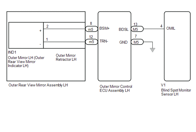
WIRING DIAGRAM
CAUTION / NOTICE / HINT
NOTICE:
When checking for DTCs, make sure that the blind spot monitor main switch (combination switch assembly) is on.
PROCEDURE
| 1. | CHECK DTC |
(a) Clear the DTCs.
Click here .gif)
(b) Recheck for DTCs and check if the same DTC is output again.
Body Electrical > Blind Spot Monitor Master > Trouble CodesOK:
DTC C1AB2 is not output.
| OK | .gif) | USE SIMULATION METHOD TO CHECK |
|
.gif)
| 2. | CHECK HARNESS AND CONNECTOR (BLIND SPOT MONITOR SENSOR LH - OUTER MIRROR CONTROL ECU ASSEMBLY LH) |
| (a) Disconnect the blind spot monitor sensor LH connector. |
|
.png)
(b) Disconnect the M5 outer mirror control ECU assembly LH connector.
(c) Measure the resistance according to the value(s) in the table below.
Standard Resistance:
| Tester Connection | Condition | Specified Condition |
|---|---|---|
| V1-4 (OMIL) - Body ground | Always | 10 kΩ or higher |
| NG | | REPAIR OR REPLACE HARNESS OR CONNECTOR |
|
| 3. | CHECK OUTER REAR VIEW MIRROR ASSEMBLY LH |
| (a) Disconnect the outer rear view mirror assembly LH connector. |
|
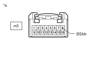
(b) Disconnect the IND1 outer mirror LH connector.
(c) Measure the resistance according to the value(s) in the table below.
Standard Resistance:
| Tester Connection | Condition | Specified Condition |
|---|---|---|
| m5-8 (BSM+) - Body ground | Always | 10 kΩ or higher |
| NG | | REPLACE OUTER MIRROR RETRACTOR LH |
|
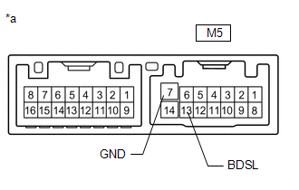
| 4. | CHECK OUTER MIRROR CONTROL ECU ASSEMBLY LH |
(a) Disconnect the outer mirror control ECU assembly LH connector.
| (b) Measure the resistance according to the value(s) in the table below. Standard Resistance:
|
|
| NG | | REPLACE OUTER MIRROR CONTROL ECU ASSEMBLY LH |
|
| 5. | INSPECT OUTER MIRROR LH |
(a) Replace the outer mirror LH.
Click here
(b) Inspect the outer rear view mirror indicator LH on the outer mirror LH.
Click here
| OK | | REPLACE BLIND SPOT MONITOR SENSOR LH |
| NG | | REPLACE OUTER MIRROR LH (OUTER REAR VIEW MIRROR INDICATOR LH) |
READ NEXT:
 Short to GND in Outer Mirror Indicator(Slave) (C1AB3)
DESCRIPTION This DTC is stored when the blind spot monitor sensor RH detects a ground short in the outer rear view mirror indicator RH. DTC No. Detection Item DTC Detection Condition Trouble
Open in Outer Mirror Indicator(Master) (C1AB4)
DESCRIPTION This DTC is stored when the blind spot monitor sensor LH detects an open in the outer rear view mirror indicator LH. DTC No. Detection Item DTC Detection Condition Trouble Area
Open in Outer Mirror Indicator(Slave) (C1AB5)
DESCRIPTION This DTC is stored when the blind spot monitor sensor RH detects an open in the outer rear view mirror indicator RH. DTC No. Detection Item DTC Detection Condition Trouble Area
SEE MORE:
Fail-safe Chart
FAIL-SAFE CHART FAIL-SAFE FUNCTION (a) When a malfunction occurs in the road sign assist system, a message will be displayed on the multi-information display and the road sign assist system will be disabled, depending on the malfunction. Warning Message Malfunction Status Fail-safe Operation
Pointer Displayed/not Displayed Repeatedly
WIRING DIAGRAM CAUTION / NOTICE / HINT NOTICE:
Inspect the fuses for circuits related to this system before performing the following procedure.
When replacing the radio receiver assembly or navigation ECU, always replace it with a new one.
If a radio receiver assembly or navigation ECU which w
