Lexus NX: Short to GND in Outer Mirror Indicator(Slave) (C1AB3)
DESCRIPTION
This DTC is stored when the blind spot monitor sensor RH detects a ground short in the outer rear view mirror indicator RH.
| DTC No. | Detection Item | DTC Detection Condition | Trouble Area | Note |
|---|---|---|---|---|
| C1AB3 | Short to GND in Outer Mirror Indicator(Slave) | Both of the following conditions are met:
|
| - |
WIRING DIAGRAM
CAUTION / NOTICE / HINT
NOTICE:
When checking for DTCs, make sure that the blind spot monitor main switch (combination switch assembly) is on.
PROCEDURE
| 1. | CHECK DTC |
(a) Clear the DTCs.
Click here .gif)
(b) Recheck for DTCs and check if the same DTC is output again.
Body Electrical > Blind Spot Monitor Slave > Trouble CodesOK:
DTC C1AB3 is not output.
| OK | .gif) | USE SIMULATION METHOD TO CHECK |
|
.gif)
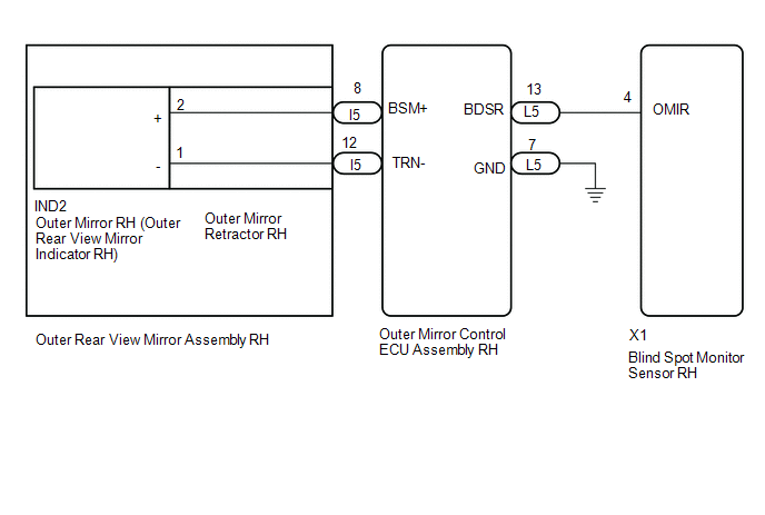
| 2. | CHECK HARNESS AND CONNECTOR (BLIND SPOT MONITOR SENSOR RH - OUTER MIRROR CONTROL ECU ASSEMBLY RH) |
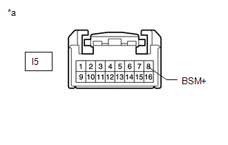
| (a) Disconnect the blind spot monitor sensor RH connector. |
|
.png)
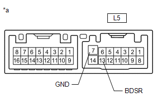
(b) Disconnect the L5 outer mirror control ECU assembly RH connector.
(c) Measure the resistance according to the value(s) in the table below.
Standard Resistance:
| Tester Connection | Condition | Specified Condition |
|---|---|---|
| X1-4 (OMIR) - Body ground | Always | 10 kΩ or higher |
| NG | | REPAIR OR REPLACE HARNESS OR CONNECTOR |
|
| 3. | CHECK OUTER REAR VIEW MIRROR ASSEMBLY RH |
| (a) Disconnect the outer rear view mirror assembly RH connector. |
|
(b) Disconnect the IND2 outer mirror RH connector.
(c) Measure the resistance according to the value(s) in the table below.
Standard Resistance:
| Tester Connection | Condition | Specified Condition |
|---|---|---|
| l5-8 (BSM+) - Body ground | Always | 10 kΩ or higher |
| NG | | REPLACE OUTER MIRROR RETRACTOR RH |
|
| 4. | CHECK OUTER MIRROR CONTROL ECU ASSEMBLY RH |
| (a) Disconnect the outer mirror control ECU assembly RH connector. |
|
(b) Measure the resistance according to the value(s) in the table below.
Standard Resistance:
| Tester Connection | Condition | Specified Condition |
|---|---|---|
| L5-13 (BDSR) - L5-7 (GND) | Always | 10 kΩ or higher |
| NG | | REPLACE OUTER MIRROR CONTROL ECU ASSEMBLY RH |
|
| 5. | INSPECT OUTER MIRROR RH |
(a) Replace the outer mirror RH.
Click here
(b) Inspect the outer rear view mirror indicator RH on the outer mirror RH.
Click here
| OK | | REPLACE BLIND SPOT MONITOR SENSOR RH |
| NG | | REPLACE OUTER MIRROR RH (OUTER REAR VIEW MIRROR INDICATOR RH) |
READ NEXT:
 Open in Outer Mirror Indicator(Master) (C1AB4)
DESCRIPTION This DTC is stored when the blind spot monitor sensor LH detects an open in the outer rear view mirror indicator LH. DTC No. Detection Item DTC Detection Condition Trouble Area
Open in Outer Mirror Indicator(Slave) (C1AB5)
DESCRIPTION This DTC is stored when the blind spot monitor sensor RH detects an open in the outer rear view mirror indicator RH. DTC No. Detection Item DTC Detection Condition Trouble Area
Blind Spot Monitor Master Module (C1AB6)
DESCRIPTION This DTC is stored when the blind spot monitor sensor LH detects an internal malfunction. DTC No. Detection Item DTC Detection Condition Trouble Area Note C1AB6 Blind Spot
SEE MORE:
Power Supply Drive Circuit (C1257)
DESCRIPTION The skid control ECU (brake booster with master cylinder assembly) detects a drop in accumulator pressure according to the signals from the accumulator pressure sensor, then operates and stops the motor relay as well as the pump motor. The skid control ECU (brake booster with master cyli
Removal
REMOVAL CAUTION / NOTICE / HINT HINT:
Use the same procedure for the RH and LH sides.
The following procedure is for the LH side.
NOTICE:
While the auxiliary battery is connected, even if the power switch is off, the brake control system activates when the brake pedal is depressed or the
