Lexus NX: SRS Warning Light Remains ON
DESCRIPTION
The SRS warning light is located in the combination meter assembly.
When the SRS is normal, the SRS warning light comes on for approximately 6 seconds after the power switch is turned from off on (IG), and then goes off automatically.
If there is a malfunction in the SRS, the SRS warning light comes on to inform the driver of a problem.
If a malfunction occurs in the airbag ECU assembly, combination meter assembly or wire harness connected to the airbag ECU assembly or combination meter assembly, the SRS warning light comes on.
The SRS is equipped with a voltage-increase circuit (DC-DC converter) in the airbag ECU assembly in case the source voltage drops.
When the auxiliary battery voltage drops, the voltage-increase circuit (DC-DC converter) functions to increase the voltage of the SRS to normal voltage.
A malfunction in this circuit is not recorded in the airbag ECU assembly. The SRS warning light automatically goes off when the source voltage returns to normal.
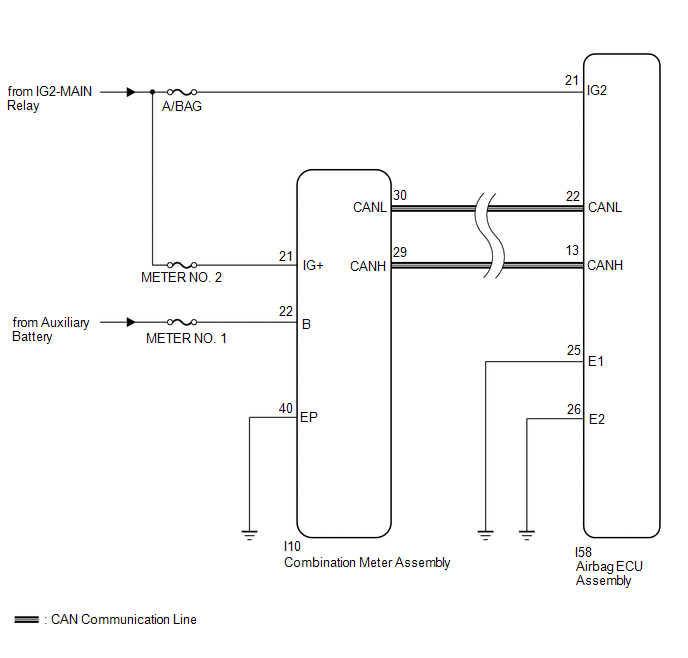
The signal to illuminate the SRS warning light is transmitted from the airbag ECU assembly to the combination meter assembly through the CAN communication system.
WIRING DIAGRAM
CAUTION / NOTICE / HINT
NOTICE:
-
After the power switch is turned off, there may be a waiting time before disconnecting the negative (-) auxiliary battery terminal.
Click here
.gif)
-
When disconnecting and reconnecting the auxiliary battery
Click here
HINT:
When disconnecting and reconnecting the auxiliary battery, there is an automatic learning function that completes learning when the respective system is used.
Click here
-
After replacing the airbag ECU assembly, refer to initialization.
Click here
- Inspect the fuses for circuits related to this system before performing the following inspection procedure.
- When replacing the combination meter assembly, make sure to replace it with a new one.
PROCEDURE
| 1. | CHECK CAN COMMUNICATION SYSTEM |
(a) Check if a CAN communication DTC is output.
Click here
| DTCs are output | .gif) | GO TO CAN COMMUNICATION SYSTEM |
|
.gif)
| 2. | CHECK AUXILIARY BATTERY |
(a) Measure the auxiliary battery voltage with the power switch off.
Standard voltage:
11 to 14 V
HINT:
It may be possible to tell whether the auxiliary battery is discharged by operating the horn.
If the voltage is below 11 V, recharge or replace the auxiliary battery before proceeding to the next step.
| NG | | REPLACE OR RECHARGE AUXILIARY BATTERY |
|
| 3. | CHECK CONNECTION OF CONNECTORS |
(a) Turn the power switch off.
(b) Disconnect the cable from the negative (-) auxiliary battery terminal, and wait for at least 90 seconds.
(c) Check that the connectors are properly connected to the airbag ECU assembly and combination meter assembly.
| The connectors are not properly connected | | CONNECT CONNECTORS PROPERLY |
|
| 4. | CHECK HARNESS AND CONNECTOR (AIRBAG ECU ASSEMBLY - BATTERY AND BODY GROUND) |
| (a) Disconnect the connectors from the airbag ECU assembly. |
|
(b) Connect the cable to the negative (-) auxiliary battery terminal, and wait for at least 2 seconds.
(c) Turn the power switch on (IG).
(d) Operate all the components of the electrical system (defogger, wipers, headlights, heater blower, etc.).
(e) Measure the voltage according to the value(s) in the table below.
Standard Voltage:
| Tester Connection | Switch Condition | Specified Condition |
|---|---|---|
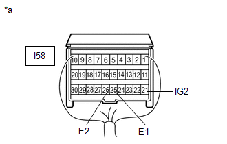
| I58-21 (IG2) - Body ground | Power switch on (IG) | 11 to 14 V |
| I58-21 (IG2) - Body ground | Power switch off | Below 1 V |
(f) Measure the resistance according to the value(s) in the table below.
Standard Resistance:
| Tester Connection | Condition | Specified Condition |
|---|---|---|
| I58-25 (E1) - Body ground | Always | Below 1 Ω |
| I58-26 (E2) - Body ground | Always | Below 1 Ω |
| NG | | REPLACE HARNESS AND CONNECTOR |
|
| 5. | CHECK HARNESS AND CONNECTOR (COMBINATION METER ASSEMBLY - BATTERY AND BODY GROUND) |
(a) Turn the power switch off.
| (b) Disconnect the cable from the negative (-) auxiliary battery terminal, and wait for at least 90 seconds. |
|
(c) Disconnect the connector from the combination meter assembly.
(d) Connect the cable to the negative (-) auxiliary battery terminal, and wait for at least 2 seconds.
(e) Turn the power switch on (IG).
(f) Measure the voltage according to the value(s) in the table below.
Standard Voltage:
| Tester Connection | Switch Condition | Specified Condition |
|---|---|---|
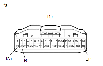
| I10-21 (IG+) - Body ground | Power switch on (IG) | 11 to 14 V |
| I10-22 (B) - Body ground | Power switch off | 11 to 14 V |
(g) Measure the resistance according to the value(s) in the table below.
Standard Resistance:
| Tester Connection | Condition | Specified Condition |
|---|---|---|
| I10-40 (EP) - Body ground | Always | Below 1 Ω |
| NG | | REPAIR OR REPLACE HARNESS OR CONNECTOR |
|
| 6. | CHECK SRS WARNING LIGHT (SHORT TO GROUND) |
(a) Turn the power switch off.
(b) Disconnect the cable from the negative (-) auxiliary battery terminal, and wait for at least 90 seconds.
(c) Connect the connector to the combination meter assembly.
(d) Connect the cable to the negative (-) auxiliary battery terminal, and wait for at least 2 seconds.
(e) Turn the power switch on (IG).
(f) Check the SRS warning light condition.
OK:
After the primary check period, the SRS warning light goes off for approximately 10 seconds and then remains on.
HINT:
The primary check period is approximately 6 seconds after the power switch is turned on (IG).
| OK | | REPLACE AIRBAG ECU ASSEMBLY |
| NG | | GO TO METER / GAUGE SYSTEM |
READ NEXT:
 SRS Warning Light does not Come ON
DESCRIPTION Refer to "SRS Warning Light Remains ON" Click here WIRING DIAGRAM Refer to "SRS Warning Light Remains ON" Click here CAUTION / NOTICE / HINT NOTICE:
After the power switch is turned
Components
COMPONENTS ILLUSTRATION *1 DECK FLOOR BOX LH *2 NO. 3 DECK BOARD SUB-ASSEMBLY *3 REAR DECK FLOOR BOX *4 AUXILIARY BATTERY NEGATIVE TERMINAL N*m (kgf*cm, ft.*lbf): Specified
SEE MORE:
Does not Recognize Voice Commands Performed to Contact Support Center
PROCEDURE 1. CHECK COMMUNICATION BASED VOICE RECOGNITION FUNCTION (a) While paying attention to the condition of the spoken voice command, say "Find a gas station in New York" and check that voice recognition is operating normally. HINT:
When the voice command is recognized, the content
Problem Symptoms Table
PROBLEM SYMPTOMS TABLE HINT:
Use the table below to help determine the cause of problem symptoms. If multiple suspected areas are listed, the potential causes of the symptoms are listed in order of probability in the "Suspected Area" column of the table. Check each symptom by checking the suspect
