Lexus NX: Start Up Signal Circuit between Radio Receiver Assembly and Navigation ECU
Lexus NX Service Manual / Audio & Visual & Telematics / Navigation / Multi Info Display / Navigation System / Start Up Signal Circuit between Radio Receiver Assembly and Navigation ECU
DESCRIPTION
This circuit includes the navigation ECU and radio and display receiver assembly.
WIRING DIAGRAM
PROCEDURE
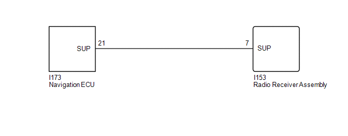
| 1. | CHECK HARNESS AND CONNECTOR (RADIO RECEIVER ASSEMBLY - NAVIGATION ECU) |
(a) Disconnect the I153 radio receiver assembly connector.
(b) Disconnect the I173 navigation ECU connector.
(c) Measure the resistance according to the value(s) in the table below.
Standard Resistance:
| Tester Connection | Condition | Specified Condition |
|---|---|---|
| I153-7 (SUP) - I173-21 (SUP) | Always | Below 1 Ω |
| I153-7 (SUP) - Body ground | Always | 10 kΩ or higher |
| OK | .gif) | PROCEED TO NEXT SUSPECTED AREA SHOWN IN PROBLEM SYMPTOMS TABLE |
.gif)
| NG | | REPAIR OR REPLACE HARNESS OR CONNECTOR |
READ NEXT:
 Microphone Circuit
DESCRIPTION
The radio receiver assembly and telephone microphone assembly are connected to each other using the microphone connection detection signal lines.
Using this circuit, the DCM (telemati
Visual Mute Signal Circuit between Radio Receiver and Multi-display
DESCRIPTION The radio receiver assembly sends a visual mute signal to the multi-display assembly. As a result, a black screen is inserted when the screen changes so that noise and distorted images are
Radio Receiver Power Source Circuit
DESCRIPTION This is the power source circuit to operate the radio receiver assembly. WIRING DIAGRAM CAUTION / NOTICE / HINT NOTICE:
Inspect the fuses for circuits related to this system before per
SEE MORE:
Disassembly
DISASSEMBLY PROCEDURE 1. REMOVE INTAKE VALVE (a) Using SST and wooden blocks, compress the inner compression spring and remove the valve spring retainer locks. SST: 09202-70020 SST: 09202-00021 (b) Remove the valve spring retainer, inner compression spring and intake valve. HINT: Arra
Problem Symptoms Table
PROBLEM SYMPTOMS TABLE NOTICE:
The following inspection procedure of the panoramic view monitor system is described on the assumption that the audio and visual system*1 or navigation system*2 is normal. If the audio and visual system*1 or navigation system*2 has any malfunction, first proceed wit
© 2016-2026 Copyright www.lexunx.com
