Lexus NX: Sound Signal Circuit between Radio Receiver and Stereo Component Amplifier
DESCRIPTION
The radio receiver assembly sends a sound signal to the stereo component amplifier assembly via this circuit.
The sound signal that is sent is amplified by the stereo component amplifier assembly, and then is sent to the speakers.
If there is an open or short in this circuit, sound cannot be heard from the speakers even if the stereo component amplifier assembly or speakers are not malfunctioning.
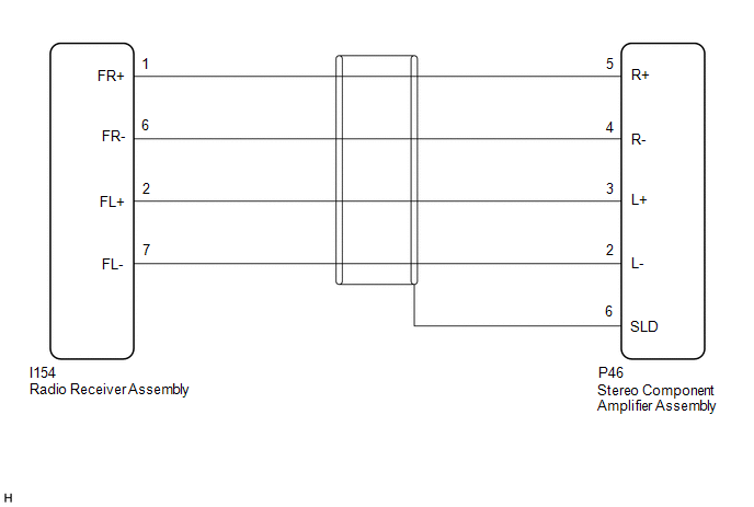
WIRING DIAGRAM
PROCEDURE
| 1. | CHECK HARNESS AND CONNECTOR (RADIO RECEIVER ASSEMBLY - STEREO COMPONENT AMPLIFIER ASSEMBLY) |
(a) Disconnect the I154 radio and display receiver assembly connector.
(b) Disconnect the P46 stereo component amplifier assembly connector.
(c) Measure the resistance according to the value(s) in the table below.
Standard Resistance:
| Tester Connection | Condition | Specified Condition |
|---|---|---|
| P46-5 (R+) - I154-1 (FR+) | Always | Below 1 Ω |
| P46-4 (R-) - I154-6 (FR-) | Always | Below 1 Ω |
| P46-3 (L+) - I154-2 (FL+) | Always | Below 1 Ω |
| P46-2 (L-) - I154-7 (FL-) | Always | Below 1 Ω |
| P46-6 (SLD) - Body ground | Always | 10 kΩ or higher |
| P46-5 (R+) or I154-1 (FR+) - Body ground | Always | 10 kΩ or higher |
| P46-4 (R-) or I154-6 (FR-) - Body ground | Always | 10 kΩ or higher |
| P46-3 (L+) or I154-2 (FL+) - Body ground | Always | 10 kΩ or higher |
| P46-2 (L-) or I154-7 (FL-) - Body ground | Always | 10 kΩ or higher |
| OK | .gif) | PROCEED TO NEXT SUSPECTED AREA SHOWN IN PROBLEM SYMPTOMS TABLE |
.gif)
| NG | | REPAIR OR REPLACE HARNESS OR CONNECTOR |
READ NEXT:
 Sound Signal Circuit between Radio Receiver and Stereo Jack Adapter
DESCRIPTION The No. 1 stereo jack adapter assembly sends the sound signal from an external device to the radio receiver assembly via this circuit. The sound signal that has been sent is amplified by t
Data Signal Circuit between Radio Receiver and Stereo Jack Adapter
DESCRIPTION The No. 1 stereo jack adapter assembly sends the sound data signal or image data signal from a USB device to the radio receiver assembly via this circuit. WIRING DIAGRAM PROCEDURE 1.
Mute Signal Circuit between Radio Receiver and Stereo Component Amplifier
DESCRIPTION This circuit sends a signal to the stereo component amplifier assembly to mute noise. Because of that, the noise produced by changing the sound source ceases. If there is an open in the ci
SEE MORE:
Initialization
INITIALIZATION RESET BACK-UP BATTERY CONDITION HINT: If the back-up battery (mobilephone battery) has been replaced, it is necessary to perform the Reset Backup Battery Condition procedure. (a) Connect the Techstream to the DLC3. (b) Turn the power switch on (IG). (c) Turn the Techstream on. (d) Ent
Taillight Relay Circuit
DESCRIPTION Illumination of the taillights and license plate light is controlled by the main body ECU (multiplex network body ECU). WIRING DIAGRAM CAUTION / NOTICE / HINT NOTICE:
Inspect the fuses for circuits related to this system before performing the following procedure.
Recognition code
