Lexus NX: Steering Angle Sensor
Components
COMPONENTS
ILLUSTRATION
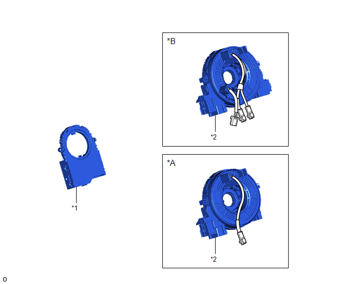
| *A | w/o Steering Heater | *B | w/ Steering Heater |
| *1 | STEERING SENSOR | *2 | SPIRAL CABLE SUB-ASSEMBLY |
Removal
REMOVAL
PROCEDURE
1. REMOVE SPIRAL W/SENSOR CABLE SUB-ASSEMBLY
Click here .gif)
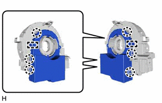
2. REMOVE STEERING SENSOR
| (a) Disengage the 6 claws and 2 pins, and remove the steering sensor from the spiral cable sub-assembly. NOTICE: Do not damage the claws and pins of the spiral cable sub-assembly. |
|
Installation
INSTALLATION
PROCEDURE
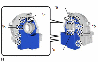
1. INSTALL STEERING SENSOR
| (a) Align the 2 pins and 2 guides, and engage the 6 claws to install the steering sensor to the spiral cable sub-assembly. NOTICE:
|
|
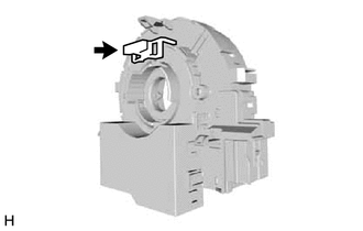
| (b) Remove the lock pin from the steering sensor. |
|
2. INSTALL SPIRAL W/SENSOR CABLE SUB-ASSEMBLY
Click here .gif)
READ NEXT:
 Components
COMPONENTS ILLUSTRATION *1 CENTER INSTRUMENT CLUSTER FINISH PANEL ASSEMBLY *2 INSTRUMENT SIDE PANEL LH *3 INSTRUMENT SIDE PANEL RH *4 LOWER NO. 1 INSTRUMENT PANEL FINISH PANEL
Removal
REMOVAL PROCEDURE 1. REMOVE CONSOLE ARMREST ASSEMBLY Click here 2. REMOVE REAR UPPER CONSOLE PANEL Click here 3. REMOVE UPPER NO. 2 CONSOLE PANEL GARNISH Click here 4. REMOVE UPPER NO. 1 C
SEE MORE:
Diagnostic Trouble Code Chart
DIAGNOSTIC TROUBLE CODE CHART Navigation System DTC No. Detection Item Link B1323 Lost Communication with Haptic Device B1324 Lost Communication with Meter B1325 Lost Communication with HUD B1326 Lost Communication with Clock Device (Local-CAN)
Terminals Of Ecu
TERMINALS OF ECU NOTICE:
Turning the power switch on (IG) with connectors disconnected may cause DTCs to be stored. Make sure to clear the DTCs after inspection has been performed.
Do not apply excessive force to the millimeter wave radar sensor assembly connector.
CHECK MILLIMETER WAVE RAD
© 2016-2026 Copyright www.lexunx.com
