Lexus NX: Accessory Socket System
Parts Location
PARTS LOCATION
ILLUSTRATION
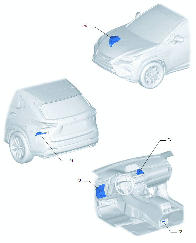
| *1 | VOLTAGE INVERTER ASSEMBLY | *2 | NO. 2 POWER OUTLET SOCKET ASSEMBLY |
| *3 | INSTRUMENT PANEL JUNCTION BLOCK ASSEMBLY - ECU-IG NO.1 FUSE | *4 | NO. 2 ENGINE ROOM RELAY BLOCK - INV FUSE |
| *5 | NO. 3 RELAY BLOCK - INV RELAY | - |
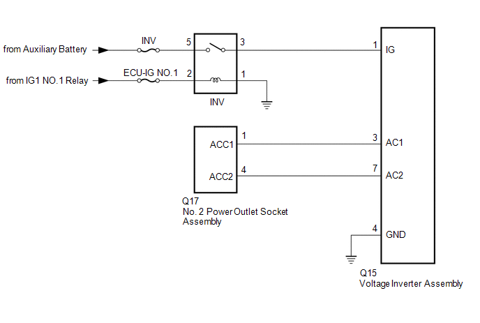
System Diagram
SYSTEM DIAGRAM
Problem Symptoms Table
PROBLEM SYMPTOMS TABLE
HINT:
Use the table below to help determine the cause of problem symptoms. If multiple suspected areas are listed, the potential causes of the symptoms are listed in order of probability in the "Suspected Area" column of the table. Check each symptom by checking the suspected areas in the order they are listed. Replace parts as necessary.
Accessory Socket System| Symptom | Suspected Area | Link |
|---|---|---|
| Electrical device connected to accessory socket system does not operate (operates normally when used with household electrical outlet) | Refer to the owner's manual of the electrical device connected to check if it can be used with the accessory socket system. | - |
| INV fuse and ECU-IG NO.1 fuse | | |
| INV relay | | |
| No. 2 power outlet socket assembly | | |
| Voltage inverter assembly | |
.gif)
READ NEXT:
 Power Outlet Socket
ComponentsCOMPONENTS ILLUSTRATION *A w/ Rear Seat Heater - - *1 CIGARETTE LIGHTER COVER *2 NO. 2 POWER OUTLET SOCKET ASSEMBLY *3 REAR CONSOLE END PANEL SUB-ASSEMBLY - -
Components
COMPONENTS ILLUSTRATION *1 DECK TRIM SIDE PANEL ASSEMBLY LH *2 LUGGAGE HOLD BELT STRIKER ASSEMBLY *3 NO. 1 LUGGAGE COMPARTMENT TRIM HOOK *4 REAR DOOR OPENING TRIM WEATHERSTRIP LH
SEE MORE:
Front Airbag Sensor Lost Communication (RH) (B1612,B1613)
DESCRIPTION The front airbag sensor RH circuit consists of the airbag ECU assembly and front airbag sensor RH. The front airbag sensor RH detects impacts to the vehicle and sends signals to the airbag ECU assembly to determine if the airbag should be deployed. DTC B1612 or B1613 is stored when a mal
Customize Parameters
CUSTOMIZE PARAMETERS CUSTOMIZE INTELLIGENT CLEARANCE SONAR SYSTEM (a) Customizing with the Techstream. NOTICE:
When the customer requests a change in a function, first make sure that the function can be customized.
Be sure to make a note of the current settings before customizing.
When troubl
