Lexus NX: Components
COMPONENTS
ILLUSTRATION
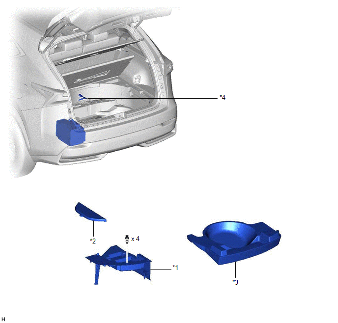
| *1 | DECK FLOOR BOX LH | *2 | NO. 3 DECK BOARD SUB-ASSEMBLY |
| *3 | REAR DECK FLOOR BOX | *4 | NEGATIVE AUXILIARY BATTERY TERMINAL |
.png) | N*m (kgf*cm, ft.*lbf): Specified torque | - | - |
ILLUSTRATION
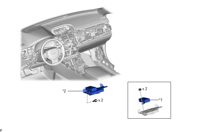
| *1 | STEREO COMPONENT EQUALIZER ASSEMBLY | *2 | STEREO COMPONENT EQUALIZER ASSEMBLY WITH BRACKET |
READ NEXT:
 Removal
REMOVAL PROCEDURE 1. REMOVE DECK BOARD ASSEMBLY Click here 2. REMOVE NO. 3 DECK BOARD SUB-ASSEMBLY Click here 3. REMOVE REAR DECK FLOOR BOX Click here 4. REMOVE DECK FLOOR BOX LH Click here 5.
Installation
INSTALLATION PROCEDURE 1. INSTALL STEREO COMPONENT EQUALIZER ASSEMBLY (a) Install the stereo component equalizer assembly with 2 nuts. 2. INSTALL STEREO COMPONENT EQUALIZER ASSEMBLY WITH BRACKET (a
Asc Speaker
ComponentsCOMPONENTS ILLUSTRATION *1 NO. 1 SPEAKER ASSEMBLY WITH BOX - - RemovalREMOVAL PROCEDURE 1. REMOVE CONSOLE BOX ASSEMBLY Click here 2. REMOVE NO. 1 SPEAKER ASSEMBLY WITH BOX
SEE MORE:
Check Bus 5 Line for Short to GND
DESCRIPTION There may be a short circuit between one of the CAN bus lines and GND when there is no resistance between terminal 15 (CA5H) of the central gateway ECU (network gateway ECU) and terminal 4 (CG) of the DLC3, or terminal 16 (CA5L) of the central gateway ECU (network gateway ECU) and termin
Hybrid Generator Performance (P0A92-261)
DTC SUMMARY MALFUNCTION DESCRIPTION This DTC indicates that magnetic force deterioration of the permanent magnet located in the rotor inside the generator has been detected. The cause of this malfunction may be one of the following: Area Main Malfunction Description Step Inverter low-volt
© 2016-2026 Copyright www.lexunx.com
