Lexus NX: Stereo Jack Adapter Light does not Illuminate
DESCRIPTION
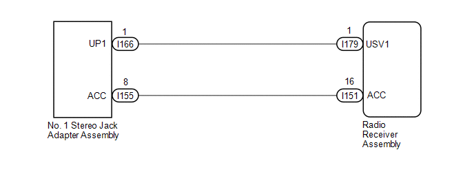
Power is supplied to the No. 1 stereo jack adapter assembly illumination from the radio receiver assembly.
WIRING DIAGRAM
CAUTION / NOTICE / HINT
NOTICE:
When replacing the radio receiver assembly, always replace it with a new one.
If a radio receiver assembly which was installed to another vehicle is used, the following may occur:
- A communication malfunction DTC may be stored.
- The radio receiver assembly may not operate normally.
HINT:
Depending on the parts that are replaced during vehicle inspection or maintenance, performing initialization, registration or calibration may be needed. Refer to Precaution for Audio and Visual System.
Click here .gif)
PROCEDURE
| 1. | CHECK HARNESS AND CONNECTOR (NO. 1 STEREO JACK ADAPTER ASSEMBLY ILLUMINATION POWER SOURCE) |
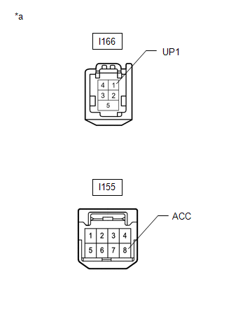
(a) Disconnect the I166 and I155 No. 1 stereo jack adapter assembly connectors.
| (b) Measure the voltage according to the value(s) in the table below. Standard Voltage:
|
|
| OK | .gif) | REPLACE NO. 1 STEREO JACK ADAPTER ASSEMBLY |
|
.gif)
| 2. | CHECK HARNESS AND CONNECTOR (RADIO RECEIVER ASSEMBLY - NO. 1 STEREO JACK ADAPTER ASSEMBLY) |
(a) Disconnect the I151 and I179 radio receiver assembly connectors.
(b) Disconnect the I155 and I166 No. 1 stereo jack adapter assembly connectors.
(c) Measure the resistance according to the value(s) in the table below.
Standard Resistance:
| Tester Connection | Condition | Specified Condition |
|---|---|---|
| I151-16 (ACC) - I155-8 (ACC) | Always | Below 1 Ω |
| I179-1 (USV1) - I166-1 (UP1) | Always | Below 1 Ω |
| I151-16 (ACC) or I155-8 (ACC) - Body ground | Always | 10 kΩ or higher |
| I179-1 (USV1) or I166-1 (UP1) - Body ground | Always | 10 kΩ or higher |
| OK | | REPLACE RADIO RECEIVER ASSEMBLY |
| NG | | REPAIR OR REPLACE HARNESS OR CONNECTOR |
READ NEXT:
 Remote Touch Screen Does not Generate Vibration Feedback
DESCRIPTION When each button displayed on the multi-display assembly is selected via remote touch screen operation, the remote touch screen generates vibration feedback according to communication betw
Switch Lights of Remote Touch do not Illuminate
DESCRIPTION Power is supplied to the remote touch illumination when the light control switch is in the tail or head position. WIRING DIAGRAM CAUTION / NOTICE / HINT NOTICE: Inspect the fuse for circu
Switch Lights of Remote Touch Always Illuminate or cannot be Controlled Using Rheostat
DESCRIPTION Power is supplied to the remote touch illumination when the light control switch is in the tail or head position. HINT:
When the remote touch is in self check mode, the switch illuminat
SEE MORE:
Inspection
INSPECTION PROCEDURE 1. INSPECT AIR CONDITIONING CONTROL ASSEMBLY (SEAT BELT WARNING LIGHT) (for Rear Side) (a) Check the seat belt warning light illumination. OK: Measurement Condition Specified Condition Battery positive (+) → Terminal 8 (IG+) Battery negative (-) → 1 (RRID) RH
Diagnosis System
DIAGNOSIS SYSTEM DESCRIPTION (a) The DCM (telematics transceiver) control the vehicle safety connect system functions. Safety connect system data and Diagnostic Trouble Codes (DTCs) can be read through the vehicle Data Link Connector 3 (DLC3). In some cases, a malfunction may be occurring in the saf
