
Lexus NX: Components
COMPONENTS
ILLUSTRATION
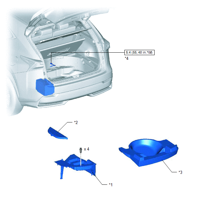
| *1 | DECK FLOOR BOX LH | *2 | NO. 3 DECK BOARD SUB-ASSEMBLY |
| *3 | REAR DECK FLOOR BOX | *4 | NEGATIVE AUXILIARY BATTERY TERMINAL |
 | N*m (kgf*cm, ft.*lbf): Specified torque | - | - |
ILLUSTRATION
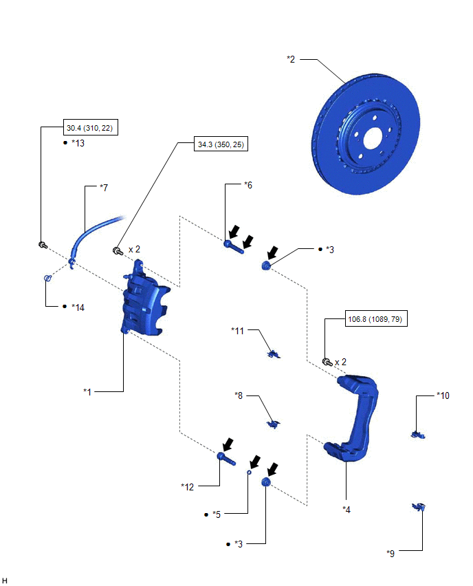
| *1 | DISC BRAKE CYLINDER ASSEMBLY LH | *2 | FRONT DISC |
| *3 | FRONT DISC BRAKE BUSH DUST BOOT | *4 | FRONT DISC BRAKE CYLINDER MOUNTING LH |
| *5 | FRONT DISC BRAKE CYLINDER SLIDE BUSH | *6 | FRONT DISC BRAKE CYLINDER SLIDE PIN |
| *7 | FRONT FLEXIBLE HOSE | *8 | FRONT NO. 1 DISC BRAKE PAD SUPPORT PLATE |
| *9 | FRONT NO. 2 DISC BRAKE PAD SUPPORT PLATE | *10 | FRONT NO. 3 DISC BRAKE PAD SUPPORT PLATE |
| *11 | FRONT NO. 4 DISC BRAKE PAD SUPPORT PLATE | *12 | NO. 2 DISC BRAKE CYLINDER SLIDE PIN |
| *13 | UNION BOLT | *14 | GASKET |
| | N*m (kgf*cm, ft.*lbf): Specified torque | ● | Non-reusable part |
 | Lithium soap base glycol grease | - | - |
ILLUSTRATION
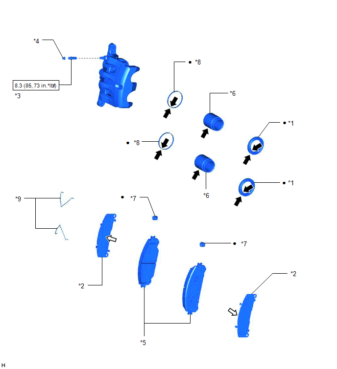
| *1 | CYLINDER BOOT | *2 | NO. 1 ANTI-SQUEAL SHIM |
| *3 | FRONT DISC BRAKE BLEEDER PLUG | *4 | FRONT DISC BRAKE BLEEDER PLUG CAP |
| *5 | FRONT DISC BRAKE PAD | *6 | FRONT DISC BRAKE PISTON |
| *7 | NO. 1 PAD WEAR INDICATOR PLATE | *8 | PISTON SEAL |
| *9 | ANTI-SQUEAL SPRING | - | - |
| | N*m (kgf*cm, ft.*lbf): Specified torque | ● | Non-reusable part |
| | Lithium soap base glycol grease |  | Disc brake grease |
READ NEXT:
 Removal
REMOVAL CAUTION / NOTICE / HINT HINT:
Use the same procedure for the RH and LH sides.
The following procedure is for the LH side.
NOTICE:
When the brake pedal is first depressed after repla
Disassembly
DISASSEMBLY CAUTION / NOTICE / HINT HINT:
Use the same procedure for the RH and LH sides.
The following procedure is for the LH side.
PROCEDURE 1. REMOVE FRONT DISC BRAKE PISTON (a) Place a
Inspection
INSPECTION PROCEDURE 1. CHECK BRAKE CYLINDER AND PISTON (a) Check the cylinder bore and piston for rust or scoring. If necessary, replace the brake cylinder and piston. 2. CHECK PAD LINING THICKNESS (
SEE MORE:
Dtc Check / Clear
DTC CHECK / CLEAR CHECK DTC (a) Connect the Techstream to the DLC3. (b) Turn the power switch on (IG). (c) Turn the Techstream on. (d) Enter the following menus: Chassis / Panoramic View Monitor / Trouble Codes. (e) Check the details of the DTCs. Click here Chassis > Panoramic View Monitor >
Sensor of Rear Motor Inverter Temperature (P0AF3-676,P0AF6-675)
DTC SUMMARY MALFUNCTION DESCRIPTION These DTCs indicate the temperature sensor value for rear motor inverter is abnormal. The cause of this malfunction may be one of the following: Internal inverter malfunction
Inverter with converter assembly internal circuit malfunction
Hybrid cooling syste
