Lexus NX: Stroke Sensor (C1247,C1346,C1392)
DESCRIPTION
The brake pedal stroke sensor assembly sends a signal about the pedal stroke to the skid control ECU (brake booster with master cylinder assembly).
DTC C1346 will be cleared when the brake pedal stroke sensor assembly sends a brake pedal stroke sensor assembly signal or when Test Mode ends. DTC C1346 is output only in Test Mode.
| DTC No. | Detection Item | INF Code | DTC Detection Condition | Trouble Area | Note |
|---|---|---|---|---|---|
| C1247 | Stroke Sensor | 211 212 213 214 215 216 217 218 219 220 221 222 223 |
|
| - |
| C1346 | Abnormal Learning of Stroke Sensor Zero Point | - | Detected only during Test Mode. |
| - |
| C1392 | Zero Point Calibration of Stroke Sensor undone | - | Zero point calibration of brake pedal stroke sensor assembly is unfinished. |
| - |
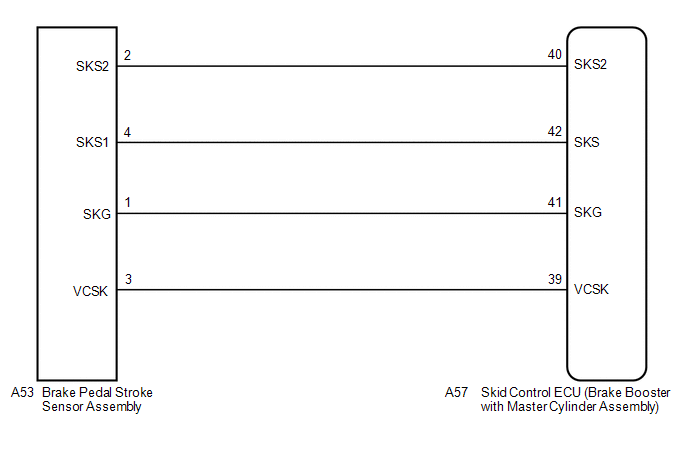
WIRING DIAGRAM
CAUTION / NOTICE / HINT
NOTICE:
When replacing the skid control ECU (brake booster with master cylinder assembly) or brake pedal stroke sensor assembly, perform initialization and calibration of the linear solenoid valve.
Click here .gif)
HINT:
Check the condition of each related circuit connector before troubleshooting.
Click here
PROCEDURE
| 1. | CHECK BRAKE PEDAL |
(a) Check that the brake pedal and the brake pedal stroke sensor assembly are properly installed and that the pedal can be depressed normally.
(b) Check and adjust the brake pedal height.
Click here
(c) Adjust the brake pedal stroke sensor assembly.
Click here
|
.gif)
| 2. | CHECK HARNESS AND CONNECTOR (BRAKE BOOSTER WITH MASTER CYLINDER ASSEMBLY - BRAKE PEDAL STROKE SENSOR ASSEMBLY) |
(a) Make sure that there is no looseness at the locking part and the connecting part of the connectors.
(b) Disconnect the A57 skid control ECU (brake booster with master cylinder assembly) connector.
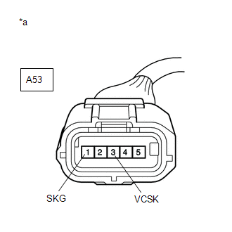
(c) Disconnect the A53 brake pedal stroke sensor assembly connector.
(d) Check both the connector case and the terminal for deformation and corrosion.
OK:
No deformation or corrosion.
(e) Measure the resistance according to the value(s) in the table below.
Standard Resistance:
| Tester Connection | Condition | Specified Condition |
|---|---|---|
| A57-39 (VCSK) - A53-3 (VCSK) | Always | Below 1 Ω |
| A57-39 (VCSK) or A53-3 (VCSK) - Body ground | Always | 10 kΩ or higher |
| A57-41 (SKG) - A53-1 (SKG) | Always | Below 1 Ω |
| A57-41 (SKG) or A53-1 (SKG) - Body ground | Always | 10 kΩ or higher |
| A57-42 (SKS) - A53-4 (SKS1) | Always | Below 1 Ω |
| A57-42 (SKS) or A53-4 (SKS1) - Body ground | Always | 10 kΩ or higher |
| A57-40 (SKS2) - A53-2 (SKS2) | Always | Below 1 Ω |
| A57-40 (SKS2) or A53-2 (SKS2) - Body ground | Always | 10 kΩ or higher |
| NG | .gif) | REPAIR OR REPLACE HARNESS OR CONNECTOR |
|
| 3. | INSPECT BRAKE BOOSTER WITH MASTER CYLINDER ASSEMBLY (SENSOR OUTPUT) |
| (a) Reconnect the A57 skid control ECU (brake booster with master cylinder assembly) connector. |
|
(b) Turn the power switch on (IG).
(c) Measure the voltage according to the value(s) in the table below.
Standard Voltage:
| Tester Connection | Switch Condition | Specified Condition |
|---|---|---|
| A53-3 (VCSK) - A53-1 (SKG) | Power switch on (IG) | 4.84 to 5.16 V |
| OK | | REPLACE BRAKE PEDAL STROKE SENSOR ASSEMBLY |
| NG | | REPLACE BRAKE BOOSTER WITH MASTER CYLINDER ASSEMBLY |
READ NEXT:
 Open Circuit in Stop Light Switch Circuit (C1249)
DESCRIPTION The skid control ECU (brake booster with master cylinder assembly) receives the stop light switch assembly signal and detects the brake pedal operation status. The skid control ECU (brake
Brake Booster Pump Motor on Time Abnormally Long (C1252,C1253)
DESCRIPTION The skid control ECU (brake booster with master cylinder assembly) detects decreases in the accumulator pressure according to the data from the accumulator pressure sensor, and then starts
Accumulator Low Pressure (C1256)
DESCRIPTION The accumulator pressure sensor is built into the brake actuator (brake booster with master cylinder assembly) and detects the accumulator pressure. The skid control ECU (brake booster wit
SEE MORE:
Precaution
PRECAUTION NOTICE: When disassembling the headlight assembly, use static electricity countermeasures SST (desktop antistatic mat set) and observe all precautions to prevent damage to the system by electrostatic discharge (ESD). STATIC ELECTRICITY COUNTERMEASURES SST SST:Desktop antistatic mat set (0
Power Source Circuit
DESCRIPTION This circuit is the power source circuit for the stereo component equalizer assembly. WIRING DIAGRAM CAUTION / NOTICE / HINT NOTICE: Inspect the fuses for circuits related to this system before performing the following procedure. PROCEDURE 1. CHECK HARNESS AND CONNECTOR (STEREO CO
