Lexus NX: Power Source Circuit
DESCRIPTION
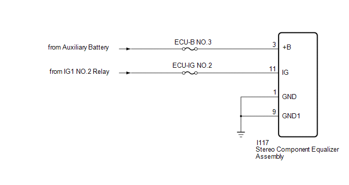
This circuit is the power source circuit for the stereo component equalizer assembly.
WIRING DIAGRAM
CAUTION / NOTICE / HINT
NOTICE:
Inspect the fuses for circuits related to this system before performing the following procedure.
PROCEDURE
| 1. | CHECK HARNESS AND CONNECTOR (STEREO COMPONENT EQUALIZER ASSEMBLY - BATTERY AND BODY GROUND) |
| (a) Disconnect the stereo component equalizer assembly connector. |
|
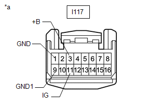
(b) Measure the resistance according to the value(s) in the table below.
Standard Resistance:
| Tester Connection | Condition | Specified Condition |
|---|---|---|
| I117-1 (GND) - Body ground | Always | Below 1 Ω |
| I117-9 (GND1) - Body ground | Always | Below 1 Ω |
(c) Measure the voltage according to the value(s) in the table below.
Standard Voltage:
| Tester Connection | Switch Condition | Specified Condition |
|---|---|---|
| I117-3 (+B) - Body ground | Power switch off | 11 to 14 V |
| I117-11 (IG) - Body ground | Power switch on (IG) | 11 to 14 V |
| OK | .gif) | PROCEED TO NEXT SUSPECTED AREA SHOWN IN PROBLEM SYMPTOMS TABLE |
| NG | | REPAIR OR REPLACE HARNESS OR CONNECTOR |
READ NEXT:
 Precaution
PRECAUTION PRECAUTION FOR DISCONNECTING CABLE FROM NEGATIVE AUXILIARY BATTERY TERMINAL NOTICE: After the power switch is turned off, the radio receiver assembly records various types of memory and set
Parts Location
PARTS LOCATION ILLUSTRATION *1 NO. 2 ENGINE ROOM RELAY BLOCK - DCM FUSE (w/ Manual [SOS] Switch) - ECU-B NO.5 FUSE - ECU-B NO.1 FUSE *2 NO. 1 ENGINE ROOM RELAY BLOCK - AMP FUSE - RADIO FUSE
SEE MORE:
Removal
REMOVAL CAUTION / NOTICE / HINT HINT:
Use the same procedure for the RH and LH sides.
The procedure listed below is for the LH side.
PROCEDURE 1. REMOVE OUTER MIRROR LH (a) Push the upper part of the mirror surface and tilt it. (b) Apply protective tape to the areas shown in the illustrat
Components
COMPONENTS ILLUSTRATION *1 DECK FLOOR BOX LH *2 NO. 3 DECK BOARD SUB-ASSEMBLY *3 REAR DECK FLOOR BOX *4 NEGATIVE AUXILIARY BATTERY TERMINAL N*m (kgf*cm, ft.*lbf): Specified torque - - ILLUSTRATION *A for Driver Side *B for Front Passenger Side *1 FRO
