Lexus NX: Switch Operation of Remote Touch not Accepted
CAUTION / NOTICE / HINT
NOTICE:
When replacing the radio receiver assembly, always replace it with a new one.
If a radio receiver assembly which was installed to another vehicle is used, the following may occur:
- A communication malfunction DTC may be stored.
- The radio receiver assembly may not operate normally.
HINT:
Depending on the parts that are replaced during vehicle inspection or maintenance, performing initialization, registration or calibration may be needed. Refer to Precaution for Audio and Visual System.
Click here .gif)
PROCEDURE
| 1. | START DIAGNOSTIC MODE |
(a) Activate diagnostic mode and check if the "Service Menu" screen can be displayed.
Click here
OK:
Diagnostic mode can be activated.
| NG | .gif) | GO TO STEP 3 |
|
.gif)
| 2. | CHECK PANEL SWITCH (OPERATION CHECK) |
| (a) Enter the "Panel&Steering Switch Check Mode" screen. Refer to Check Panel & Steering Switch in Operation Check. Click here |
|
.png)
(b) Operate the abnormal switch and check if the switch status is correctly displayed.
OK:
The switch status is correctly displayed as operated.
| OK | | REPLACE RADIO RECEIVER ASSEMBLY |
| NG | | GO TO STEP 3 |
| 3. | REMOTE TOUCH SELF CHECK (SWITCH OPERATION CHECK) |
(a) Enter self-diagnostic mode.
Click here
| (b) Operate the remote touch screen in the upper left to turn the switch illumination off. NOTICE: Since the remote touch screen may recognize a pinch in/out or flick operation if operated with 2 fingers, always use 1 finger to operate the remote touch in self-diagnostic mode. |
|
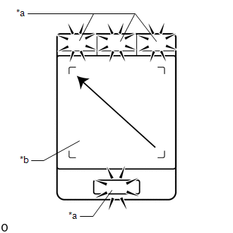
(c) With the switch illumination turned off, press each switch of the remote touch and check that the switch illumination turns on.
| Result | Proceed to |
|---|---|
| Self check mode cannot be activated. | A |
| Some switches do not turn on the switch illumination when they are pressed. | |
| All switches turn on the switch illumination when they are pressed. | B |
| A | | REPLACE REMOTE OPERATION CONTROLLER ASSEMBLY (REMOTE TOUCH) |
| B | | REPLACE RADIO RECEIVER ASSEMBLY |
READ NEXT:
 Pointer Displayed/not Displayed Repeatedly
WIRING DIAGRAM CAUTION / NOTICE / HINT NOTICE:
Inspect the fuses for circuits related to this system before performing the following procedure.
When replacing the radio receiver assembly, always
Pointer not Displayed on Screen or Pointer does not Move
CAUTION / NOTICE / HINT NOTICE: When replacing the radio receiver assembly, always replace it with a new one. If a radio receiver assembly which was installed to another vehicle is used, the following
Black Screen
PROCEDURE 1. CHECK DISPLAY SETTING (a) Check that the display is not in screen off mode. OK: The display setting is not in screen off mode. NG CHANGE SCREEN TO SCREEN ON MODE
SEE MORE:
Linear Solenoid Valve Offset Learning undone (C1345,C1368)
DESCRIPTION The skid control ECU (brake booster with master cylinder assembly) stores and corrects the individual differences in the brake pedal stroke sensor assembly, actuator solenoids, and stroke simulator solenoid. Perform initialization and calibration of the linear solenoid valve if any of th
Parts Location
PARTS LOCATION ILLUSTRATION *1 COMBINATION METER ASSEMBLY *2 CLIMATE CONTROL SWITCH (for Driver Side) *3 CLIMATE CONTROL SWITCH (for Front Passenger Side) *4 AIR CONDITIONING CONTROL ASSEMBLY *5 AIR CONDITIONING AMPLIFIER ASSEMBLY *6 DLC3 *7 INSTRUMENT PANEL JUNCT
