Lexus NX: System Description
SYSTEM DESCRIPTION
BRIEF DESCRIPTION
(a) The Controller Area Network (CAN) is a serial data communication system for real time application. It is a vehicle multiplex communication system which has a high communication speed and the ability to detect malfunctions.
(b) Using the CANH and CANL bus lines as a pair, CAN communication is performed using a voltage differential. (A base voltage is applied to the pair of lines and a voltage differential is created when communicating.)
(c) Many ECUs or sensors installed to the vehicle operate by sharing information and communicating with each other.
(d) The V bus has a termination circuit with a resistor of 60 Ω, and the bus 2, bus 3, bus 5 and sub bus 1 each have termination circuits with two resistors of 120 Ω.
DEFINITION OF TERMS
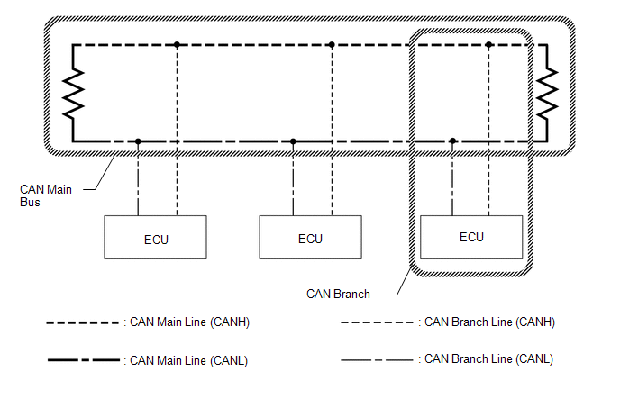
(a) Main bus
(1) The main bus is a wire harness between the two terminating resistors on the bus. This is the main bus in the CAN communication system.
(b) Branch
(1) A branch is a wire harness which diverges from the main bus to an ECU or sensor.
(c) Terminating resistors
(1) Two resistors of 120 Ω are installed in parallel across the ends of the CAN main bus lines. They are called terminating resistors. These resistors allow the changes of the voltage differential between the CAN bus lines to be accurately judged. To allow proper function of CAN communication, it is necessary to have both terminating resistors installed. Since the two resistors are installed in parallel, this results in a measurement of approximately 60 Ω.
CIRCUIT DESCRIPTION
(a) The V bus has a termination circuit with a resistor of 60 Ω.
(b) The bus 2, bus 3, bus 5 and sub bus 1 each have termination circuits with two resistors of 120 Ω.
TROUBLESHOOTING REMARKS
(a) DTCs for the CAN communication system can be checked using the Techstream. The DLC3 is connected to the CAN communication system, but no DTCs exist regarding problems in the DLC3 or the DLC3 branch lines. If there is a malfunction in the DLC3 or the DLC3 branch lines, ECUs on the CAN cannot output DTCs to the Techstream.
DIAGNOSTIC TROUBLE CODES FOR CAN COMMUNICATION SYSTEM
HINT:
See Diagnosis System.
Click here .gif)
HOW TO DISTINGUISH CONNECTOR OF CAN JUNCTION CONNECTOR
(a) In the CAN communication system, the shape of connectors connected to the CAN junction connector which has an earth terminal are the same. The connectors connected to the CAN junction connector can be distinguished by the colors of the bus lines and the connecting side of the junction connector.
HINT:
See Terminals of ECU for bus line color or the shape of connectors.
Click here
READ NEXT:
 How To Proceed With Troubleshooting
CAUTION / NOTICE / HINT PRECAUTIONS WHEN TROUBLESHOOTING NOTICE:
Because the order of diagnosis is important to allow correct diagnosis, make sure to begin troubleshooting using How to Proceed with
Utility
UTILITY INITIALIZE THE CONNECTION INFORMATION OF A GATEWAY FUNCTION EQUIPPED ECU (BUS MONITOR ECU) (a) Connect the Techstream to the DLC3. (b) Turn the power switch on (IG). (c) Turn the Techstream on
Problem Symptoms Table
PROBLEM SYMPTOMS TABLE HINT:
Use the table below to help determine the cause of problem symptoms. If multiple suspected areas are listed, the potential causes of the symptoms are listed in order of
SEE MORE:
Before driving
Observe the following before starting
off in the vehicle to ensure
safety of driving.
Installing floor mats
Use only floor mats designed specifically
for vehicles of the same model
and model year as your vehicle. Fix
them securely in place onto the carpet.
1. Insert the retaining hooks (clip
Reassembly
REASSEMBLY CAUTION / NOTICE / HINT HINT: Perform "Inspection After Repairs" after replacing the piston or piston ring. Click here PROCEDURE 1. INSTALL STUD BOLT NOTICE: If a stud bolt is deformed or its threads are damaged, replace it. (a) Using an E8 "TORX" socket wrench, install the stud bolt
