- Inverter W/P Revolution
- (Inverter) W/P Run Control Duty
- Ready Signal
Lexus NX: Inverter Coolant Pump Speed Signal (P314A-828)
Lexus NX Service Manual / Engine & Hybrid System / 2ar-fxe (hybrid / Battery Control) / Hybrid Control System / Inverter Coolant Pump Speed Signal (P314A-828)
DESCRIPTION
Refer to the description for DTC P0C73-776.
Click here .gif)
The inverter water pump assembly sends the inverter water pump speed (measured value) signal to the hybrid vehicle control ECU. If the inverter water pump speed (measured value) signal is not sent to the hybrid vehicle control ECU when the power switch is on (READY), this DTC is stored.
| DTC No. | Detection Item | DTC Detection Condition | Trouble Area | MIL | Warning Indicate |
|---|---|---|---|---|---|
| P314A-828 | Inverter Coolant Pump Speed Signal | The inverter water pump speed signal is not sent to the hybrid vehicle control ECU when the power switch is turned on (READY). (1 trip detection logic) |
| Comes on | Master Warning Light: Comes on |
HINT:
- A malfunction (open, short to +B or short to ground) in the speed signal line from the inverter water pump assembly to the hybrid vehicle control ECU is detected.
- A malfunction in the inverter water pump assembly power source circuit is detected.
- A malfunction in the +B line is detected.
- A malfunction in hybrid vehicle control ECU power source circuit is detected.
| DTC No. | Data List |
|---|---|
| P314A-828 | |
| DTC No. | Active Test |
|---|---|
| P314A-828 | Activate the (Inverter) Water Pump |
MONITOR DESCRIPTION
The hybrid vehicle control ECU monitors the speed of the inverter water pump assembly. If the inverter water pump speed signal is not sent to the hybrid vehicle control ECU, the hybrid vehicle control ECU will illuminate the MIL and store a DTC.
MONITOR STRATEGY
| Related DTCs | P314A (INF 828): Water pump malfunction |
| Required sensors/components | Inverter Water Pump Assembly |
| Frequency of operation | Continuous |
| Duration | TMC's intellectual property |
| MIL operation | Immediately |
| Sequence of operation | None |
TYPICAL ENABLING CONDITIONS
| The monitor will run whenever the following DTCs are not stored | TMC's intellectual property |
| Other conditions belong to TMC's intellectual property | - |
TYPICAL MALFUNCTION THRESHOLDS
| TMC's intellectual property | - |
COMPONENT OPERATING RANGE
| Hybrid vehicle control ECU | DTC P314A (INF 828) is not detected |
CONFIRMATION DRIVING PATTERN
- Connect the Techstream to the DLC3.
- Turn the power switch on (IG) and turn the Techstream on.
- Clear the DTCs (even if no DTCs are stored, perform the clear DTC procedure).
- Turn the power switch off and wait for 30 seconds or more.
- Turn the power switch on (IG) and turn the Techstream on.
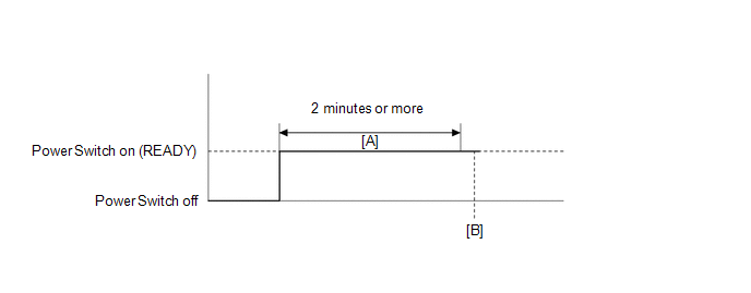
- Turn the power switch on (READY) and wait for 2 minutes or more. [A]
- Enter the following menus: Powertrain / Hybrid Control / Trouble Codes. [B]
-
Read the current DTCs.
HINT:
- If a current DTC is output, the system is malfunctioning.
- If current DTCs are not output, perform the following steps to check for permanent DTCs.
- Check that the permanent DTCs are cleared.
- If the permanent DTCs are not cleared, perform a universal trip, and then check for permanent DTCs again.
WIRING DIAGRAM
Refer to the wiring diagram for DTC P0C73-776.
Click here
CAUTION / NOTICE / HINT
NOTICE:
If DTC P0A78-284, 286, P0A7A-322, 324, P0A94-553 or 557 is output, replace the inverter with converter assembly after this inspection.
HINT:
After the repair, clear the DTCs and perform the following procedure to check that DTCs are not output.
- Turn the power switch on (READY) and wait for 2 minutes or more.
PROCEDURE
| 1. | CLEAR DTC |
Click here
|
.gif)
| 2. | PERFORM ACTIVE TEST USING TECHSTREAM (ACTIVATE THE (INVERTER) WATER PUMP) |
NOTICE:
Be sure to perform the inspection with the auxiliary battery voltage at 11 V or more.
HINT:
When the auxiliary battery voltage is low, the inverter water pump assembly may not operate.
(a) Connect the Techstream to the DLC3.
(b) Turn the power switch on (IG).
(c) Enter the following menus: Powertrain / Hybrid Control / Active Test / Activate the (Inverter) Water Pump.
Powertrain > Hybrid Control > Active Test| Tester Display |
|---|
| Activate the (Inverter) Water Pump |
(d) Perform the "Activate the (Inverter) Water Pump" Active Test.
(e) Touch the inverter water pump assembly and check that it is operating (vibrating).
OK:
The inverter water pump is operating (vibrating).
(f) Turn the power switch off.
| NG | .gif) | GO TO STEP 9 |
|
| 3. | CHECK CONNECTOR CONNECTION CONDITION (HYBRID VEHICLE CONTROL ECU CONNECTOR) |
Click here
| NG | | CONNECT SECURELY |
|
| 4. | CHECK CONNECTOR CONNECTION CONDITION (INVERTER WATER PUMP ASSEMBLY CONNECTOR) |
Click here
| NG | | CONNECT SECURELY |
|
| 5. | CHECK HARNESS AND CONNECTOR (HYBRID VEHICLE CONTROL ECU - INVERTER WATER PUMP ASSEMBLY) |
(a) Disconnect the A60 hybrid vehicle control ECU connector.
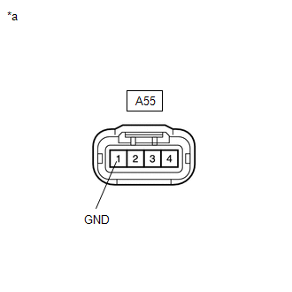
(b) Disconnect the A55 inverter water pump assembly connector.
(c) Measure the resistance according to the value(s) in the table below.
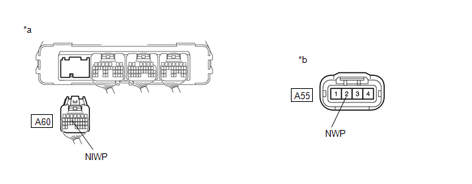
| *a | Rear view of wire harness connector (to Hybrid Vehicle Control ECU) | *b | Front view of wire harness connector (to Inverter Water Pump Assembly) |
Standard Resistance:
| Tester Connection | Condition | Specified Condition |
|---|---|---|
| A60-14 (NIWP) - A55-2 (NWP) | Power switch off | Below 1 Ω |
| A60-14 (NIWP) or A55-2 (NWP) -Body ground and other terminals | Power switch off | 10 kΩ or higher |
(d) Reconnect the A55 inverter water pump assembly connector.
(e) Reconnect the A60 hybrid vehicle control ECU connector.
| NG | | REPAIR OR REPLACE HARNESS OR CONNECTOR |
|
| 6. | CHECK HYBRID VEHICLE CONTROL ECU |
(a) Disconnect the A55 inverter water pump assembly connector.
(b) Turn the power switch on (IG).
| (c) Measure the voltage according to the value(s) in the table below. Standard Voltage:
|
|
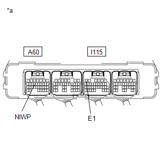
(d) Turn the power switch off.
(e) Reconnect the A55 inverter water pump assembly connector.
| NG | | REPLACE HYBRID VEHICLE CONTROL ECU |
|
| 7. | CLEAR DTC |
Click here
|
| 8. | PERFORM ACTIVE TEST USING TECHSTREAM (ACTIVATE THE (INVERTER) WATER PUMP) |
NOTICE:
Be sure to perform the inspection with the auxiliary battery voltage at 11 V or more.
HINT:
When the auxiliary battery voltage is low, the inverter water pump assembly may not operate.
(a) Connect the Techstream to the DLC3.
(b) Turn the power switch on (IG).
(c) Enter the following menus: Powertrain / Hybrid Control / Active Test / Activate the (Inverter) Water Pump.
Powertrain > Hybrid Control > Active Test| Tester Display |
|---|
| Activate the (Inverter) Water Pump |
(d) Perform the "Activate the (Inverter) Water Pump" Active Test.
| (e) Connect an oscilloscope between the hybrid vehicle control ECU terminals specified in the table below, and measure the waveform.
OK: The duration of wavelength A is 300 msec or less. |
|
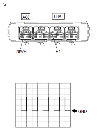
(f) Turn the power switch off.
| OK | | REPLACE HYBRID VEHICLE CONTROL ECU |
| NG | | REPLACE INVERTER WATER PUMP ASSEMBLY |
| 9. | CHECK CONNECTOR CONNECTION CONDITION (INVERTER WATER PUMP ASSEMBLY CONNECTOR) |
Click here
| NG | | CONNECT SECURELY (INVERTER WATER PUMP ASSEMBLY CONNECTOR) |
|
| 10. | CHECK INSTALLATION CONDITION (INV W/PMP RELAY) |
| (a) Check installation condition of the INV W/PMP relay. OK: INV W/PMP relay is installed correctly. |
|
| NG | | GO TO STEP 15 |
|
| 11. | CHECK HARNESS AND CONNECTOR (IGCT RELAY - INV W/PMP RELAY) |
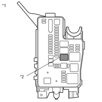
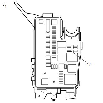
(a) Remove the IGCT relay and INV W/PMP relay from the No. 1 engine room relay block.
(b) Measure the resistance according to the value(s) in the table below.
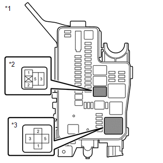
| *1 | No. 1 Engine Room Relay Block |
| *2 | INV W/PMP Relay |
| *3 | IGCT Relay |
Standard Resistance:
| Tester Connection | Condition | Specified Condition |
|---|---|---|
| 5 (IGCT relay) - 1 (INV W/PMP relay) | Power switch off | Below 1 Ω |
NOTICE:
Do not apply excessive force when using the probes of the tester to perform the inspection. If excessive force is used, the terminals will be damaged.
HINT:
-
Connectors
Slightly shake the connector vertically and horizontally.
-
Wire Harness
Slightly shake the wire harness vertically and horizontally.
The connector joint and fulcrum of the vibration are the major areas that should be checked thoroughly.
-
No. 1 engine room relay block
Apply slight vibration with a finger to the No. 1 engine room relay block and check whether a malfunction occurs.
-
INV W/PMP NO. 2 fuse
Apply slight vibration with a finger to the INV W/PMP NO. 2 fuse and check whether a malfunction occurs.
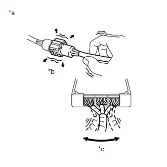
| *a | Example |
| *b | Shake Slightly |
| *c | Vibrate Slightly |
(c) Install the IGCT relay and INV W/PMP relay.
| NG | | GO TO STEP 16 |
|
| 12. | INSPECT RELAY (INV W/PMP) |
| (a) Remove the INV W/PMP relay from the No. 1 engine room relay block. |
|
| (b) Measure the resistance according to the value(s) in the table below. Standard Resistance:
|
|
.png)
(c) Install the INV W/PMP relay.
| NG | | GO TO STEP 18 |
|
| 13. | CHECK HARNESS AND CONNECTOR (INVERTER WATER PUMP ASSEMBLY - BODY GROUND) |
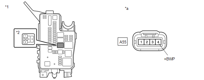
(a) Disconnect the A55 inverter water pump assembly connector.
(b) Measure the voltage according to the value(s) in the table below.
Standard Voltage:
| Tester Connection | Switch Condition | Specified Condition |
|---|---|---|
| A55-4 (+BWP) - Body ground | Power switch on (IG) | 11 to 14 V |
NOTICE:
- Do not apply excessive force when using the probes of the tester to perform the inspection. If excessive force is used, the holders will be damaged.
- Turning the power switch on (IG) with the inverter water pump with motor assembly connector disconnected causes other DTCs to be stored. Clear the DTCs after performing this inspection.
HINT:
-
Connectors
Slightly shake the connector vertically and horizontally.
-
Wire Harness
Slightly shake the wire harness vertically and horizontally.
The connector joint and fulcrum of the vibration are the major areas that should be checked thoroughly.
-
No. 1 engine room relay block
Apply slight vibration with a finger to the No. 1 engine room relay block and check whether a malfunction occurs.
-
INV W/PMP fuse
Apply slight vibration with a finger to the INV W/PMP fuse and check whether a malfunction occurs.
-
INV W/PMP relay
Apply slight vibration with a finger to the INV W/PMP relay and check whether a malfunction occurs.
| *a | Example |
| *b | Shake Slightly |
| *c | Vibrate Slightly |
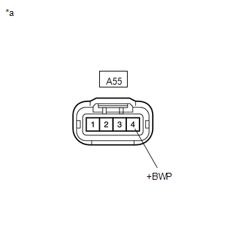
| *a | Front view of wire harness connector (to Inverter Water Pump Assembly) |
(c) Reconnect the A55 inverter water pump assembly connector.
| NG | | GO TO STEP 19 |
|
| 14. | CHECK HARNESS AND CONNECTOR (INVERTER WATER PUMP ASSEMBLY - BODY GROUND) |
(a) Disconnect the A55 inverter water pump assembly connector.
| (b) Measure the resistance according to the value(s) in the table below. Standard Resistance:
|
|
(c) Reconnect the A55 inverter water pump assembly connector.
| OK | | REPLACE INVERTER WATER PUMP ASSEMBLY |
| NG | | REPAIR OR REPLACE HARNESS OR CONNECTOR |
| 15. | INSPECT RELAY (INV W/PMP) |
| (a) Remove the INV W/PMP relay from the No. 1 engine room relay block. |
|
| (b) Measure the resistance according to the value(s) in the table below. Standard Resistance:
|
|
(c) Install the INV W/PMP relay.
| OK | | CONNECT SECURELY (INV W/PMP RELAY) |
| NG | | REPLACE RELAY (INV W/PMP) |
| 16. | CHECK INSTALLATION CONDITION (INV W/PMP NO. 2 FUSE) |
| (a) Check installation condition of the INV W/PMP NO. 2 fuse. OK: INV W/PMP NO. 2 fuse is installed correctly. |
|
| NG | | GO TO STEP 23 |
|
| 17. | CHECK FUSE (INV W/PMP NO. 2 FUSE) |
| (a) Remove the INV W/PMP NO. 2 fuse from the No. 1 engine room relay block. |
|
(b) Measure the resistance according to the value(s) in the table below.
Standard Resistance:
| Tester Connection | Condition | Specified Condition |
|---|---|---|
| INV W/PMP NO. 2 fuse | Always | Below 1 Ω |
(c) Install the INV W/PMP NO. 2 fuse.
| OK | | REPAIR OR REPLACE HARNESS OR CONNECTOR |
| NG | | GO TO STEP 24 |
| 18. | CHECK RELAY HOLDER TERMINAL (INV W/PMP RELAY) |
(a) Check the terminals of the INV W/PMP relay holder.
OK:
The terminals of the INV W/PMP relay holder are not bent, loose or corroded.
| OK | | REPLACE RELAY (INV W/PMP) |
| NG | | GO TO STEP 25 |
| 19. | CHECK INSTALLATION CONDITION (INV W/PMP FUSE) |
| (a) Check installation condition of the INV W/PMP fuse. OK: INV W/PMP fuse is installed correctly. |
|
| NG | | CONNECT SECURELY |
|
| 20. | INSPECT RELAY (INV W/PMP) |
| (a) Remove the INV W/PMP relay from the No. 1 engine room relay block. |
|
| (b) Measure the resistance according to the value(s) in the table below. Standard Resistance:
|
|
(c) Install the INV W/PMP relay.
| NG | | GO TO STEP 26 |
|
| 21. | CHECK HARNESS AND CONNECTOR (INVERTER WATER PUMP ASSEMBLY - NO. 1 ENGINE ROOM RELAY BLOCK) |
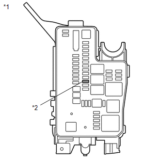
(a) Remove the INV W/PMP relay from the No. 1 engine room relay block.
(b) Disconnect the A55 inverter water pump assembly connector.
(c) Measure the resistance according to the value(s) in the table below.
| *1 | No. 1 Engine Room Relay Block | *2 | INV W/PMP relay |
| *a | Front view of wire harness connector (to Inverter Water Pump Assembly) | - | - |
Standard Resistance:
| Tester Connection | Condition | Specified Condition |
|---|---|---|
| A55-4 (+BWP) - 3 (INV W/PMP relay) | Power switch off | Below 1 Ω |
| A55-4 (+BWP) or 3 (INV W/PMP relay) - Body ground and other terminals | Power switch off | 10 kΩ or higher |
NOTICE:
Do not apply excessive force when using the probes of the tester to perform the inspection. If excessive force is used, the terminals will be damaged.
(d) Install the INV W/PMP relay.
(e) Reconnect the A55 inverter water pump assembly connector.
| NG | | REPAIR OR REPLACE HARNESS OR CONNECTOR |
|
| 22. | CHECK FUSE (INV W/PMP FUSE) |
| (a) Remove the INV W/PMP fuse from the No. 1 engine room relay block. |
|
(b) Measure the resistance according to the value(s) in the table below.
Standard Resistance:
| Tester Connection | Condition | Specified Condition |
|---|---|---|
| INV W/PMP fuse | Always | Below 1 Ω |
(c) Install the INV W/PMP fuse.
| OK | | REPAIR OR REPLACE HARNESS OR CONNECTOR |
| NG | | GO TO STEP 28 |
| 23. | INSPECT RELAY (INV W/PMP) |
| (a) Remove the INV W/PMP relay from the No. 1 engine room relay block. |
|
| (b) Measure the resistance according to the value(s) in the table below. Standard Resistance:
|
|
(c) Install the INV W/PMP relay.
| OK | | CONNECT SECURELY (INV W/PMP NO. 2 FUSE) |
| NG | | GO TO STEP 29 |
| 24. | CHECK FUSE HOLDER TERMINAL (INV W/PMP NO. 2 FUSE) |
(a) Check the terminals of the INV W/PMP NO. 2 fuse holder.
OK:
The terminals of the INV W/PMP NO. 2 fuse holder are not bent, loose or corroded.
| OK | | REPLACE FUSE (INV W/PMP NO. 2) |
| NG | | GO TO STEP 30 |
| 25. | REPAIR OR REPLACE HARNESS OR CONNECTOR |
(a) Repair or replace the terminals of the INV W/PMP relay holder.
| NEXT | | REPLACE RELAY (INV W/PMP) |
| 26. | CHECK RELAY HOLDER TERMINAL (INV W/PMP NO. 2 RELAY) |
(a) Check the terminals of the INV W/PMP relay holder.
OK:
The terminals of the INV W/PMP relay holder are not bent, loose or corroded.
| NG | | GO TO STEP 31 |
|
| 27. | CHECK FUSE (INV W/PMP NO. 2 FUSE) |
| (a) Remove the INV W/PMP NO. 2 fuse from the No. 1 engine room relay block. |
|
(b) Measure the resistance according to the value(s) in the table below.
Standard Resistance:
| Tester Connection | Condition | Specified Condition |
|---|---|---|
| INV W/PMP NO. 2 fuse | Always | Below 1 Ω |
(c) Install the INV W/PMP NO. 2 fuse.
| OK | | REPLACE RELAY (INV W/PMP) |
| NG | | GO TO STEP 33 |
| 28. | REPLACE INVERTER WATER PUMP ASSEMBLY |
Click here
| NEXT | | REPLACE FUSE (INV W/PMP) |
| 29. | REPLACE RELAY (INV W/PMP) |
(a) Replace INV W/PMP relay.
| NEXT | | CONNECT SECURELY (INV W/PMP NO. 2 FUSE) |
| 30. | REPAIR OR REPLACE HARNESS OR CONNECTOR |
(a) Repair or replace the terminals of the INV W/PMP NO. 2 fuse holder.
| NEXT | | REPLACE FUSE (INV W/PMP NO. 2) |
| 31. | CHECK FUSE (INV W/PMP NO. 2 FUSE) |
| (a) Remove the INV W/PMP NO. 2 fuse from the No. 1 engine room relay block. |
|
(b) Measure the resistance according to the value(s) in the table below.
Standard Resistance:
| Tester Connection | Condition | Specified Condition |
|---|---|---|
| INV W/PMP NO. 2 fuse | Always | Below 1 Ω |
(c) Install the INV W/PMP NO. 2 fuse.
| NG | | GO TO STEP 34 |
|
| 32. | REPAIR OR REPLACE HARNESS OR CONNECTOR |
(a) Repair or replace the terminals of the INV W/PMP relay holder.
| NEXT | | REPLACE RELAY (INV W/PMP) |
| 33. | REPLACE RELAY (INV W/PMP) |
(a) Replace INV W/PMP relay.
| NEXT | | REPLACE FUSE (INV W/PMP NO. 2) |
| 34. | REPAIR OR REPLACE HARNESS OR CONNECTOR |
(a) Repair or replace the terminals of the INV W/PMP relay holder.
|
| 35. | REPLACE RELAY (INV W/PMP) |
(a) Replace INV W/PMP relay.
| NEXT | | REPLACE FUSE (INV W/PMP NO. 2) |
READ NEXT:
 All HV Gate Blocking Range/Performance (P321E-318)
DESCRIPTION The hybrid vehicle control ECU sends a block signal to the motor generator control ECU (MG ECU) to shutdown the power supply to the motor. When the system is not in the on (READY) state, i
Part of HV Gate Blocking Range/Performance (P321F-319)
DESCRIPTION Refer to the description for DTC P321E-318. Click here DTC No. Detection Item DTC Detection Condition Trouble Area MIL Warning Indicate P321F-319 Part of HV Gate Block
MG-ECU Power Relay Intermittent Circuit (P324E-788)
DESCRIPTION If the MG ECU, which is built into in the inverter with converter assembly, is reset due to a problem with the power source in the inverter, the hybrid vehicle control ECU will stored this
SEE MORE:
Data List / Active Test
DATA LIST / ACTIVE TEST DATA LIST NOTICE: In the table below, the values listed under "Normal Condition" are reference values. Do not depend solely on these reference values when deciding whether a part is faulty or not. HINT: Using the Techstream to read the Data List allows the values or states of
Removal
REMOVAL CAUTION / NOTICE / HINT CAUTION: The engine assembly with hybrid vehicle transaxle assembly is very heavy. Be sure to follow the procedure described in the repair manual, or the engine lifter may suddenly drop. PROCEDURE 1. REMOVE SERVICE PLUG GRIP Click here 2. REMOVE WINDSHIELD WIPER MO
© 2016-2026 Copyright www.lexunx.com
