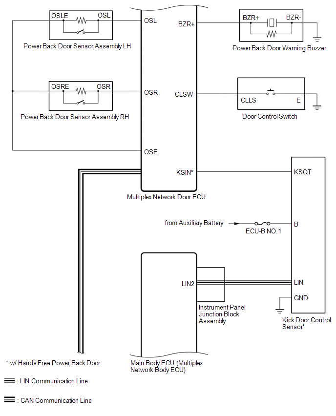
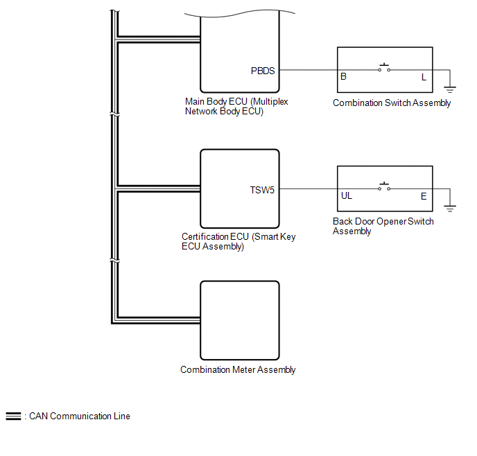
- Combination switch assembly signal
- Back door opener switch assembly signal
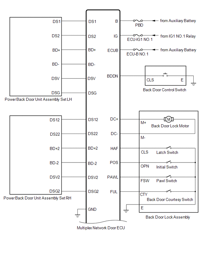
- Power back door ON/OFF signal
Lexus NX: System Diagram
SYSTEM DIAGRAM
 Communication Table
 | Transmitting ECU | Receiving ECU | Signal | Communication Method |
|---|---|---|---|
| Main body ECU (multiplex network body ECU) | Multiplex network door ECU | | CAN |
| Multiplex network door ECU | Main body ECU (multiplex network body ECU) | Back door courtesy switch signal | CAN |
| Combination meter assembly | Main body ECU (multiplex network body ECU) |
| CAN |
| Certification ECU (smart key ECU assembly) | Main body ECU (multiplex network body ECU) |
| CAN |
| Main body ECU (multiplex network body ECU) | Kick door control sensor |
| LIN |
READ NEXT:
 System Description
SYSTEM DESCRIPTION POWER BACK DOOR SYSTEM DESCRIPTION (a) The power back door system controls the power back door by automatically opening and closing the power back door with a motor. (1) The power b
How To Proceed With Troubleshooting
CAUTION / NOTICE / HINT HINT:
The power back door system troubleshooting procedure is based on the premise that the smart access system with push-button start (for Entry Function) is operating norm
Operation Check
OPERATION CHECK CHECK BASIC OPERATION NOTICE:
This check is possible only when the "Power Back Door Function" customization setting using the multi-information display in the combination meter asse
SEE MORE:
Headlight Beam Level Control Motor LH Malfunction (B2417,B2418)
DESCRIPTION DTC No. Detection Item DTC Detection Condition Trouble Area B2417 Headlight Beam Level Control Motor LH Malfunction
Power switch on (IG)
Malfunction in headlight leveling motor LH
10 seconds or more
Headlight unit assembly LH B2418 Headlight Bea
Lost Communication with Cruise Control Front Distance Range Sensor Single Sensor or Center Missing Message (U023587)
DESCRIPTION The forward recognition camera communicates with the millimeter wave radar sensor assembly via CAN communication. If a communication malfunction between the forward recognition camera and millimeter wave radar sensor assembly is detected, DTC U023587 is stored. DTC No. Detection Ite
© 2016-2026 Copyright www.lexunx.com
