- Short in PIM circuit to ground
- Short in PIM circuit to E2 circuit
- Open in VC circuit
Lexus NX: Manifold Absolute Pressure / Barometric Pressure Circuit Low Input (P0107,P0108)
Lexus NX Service Manual / Engine & Hybrid System / 2ar-fxe (engine Control) / Sfi System / Manifold Absolute Pressure / Barometric Pressure Circuit Low Input (P0107,P0108)
DESCRIPTION
.png)
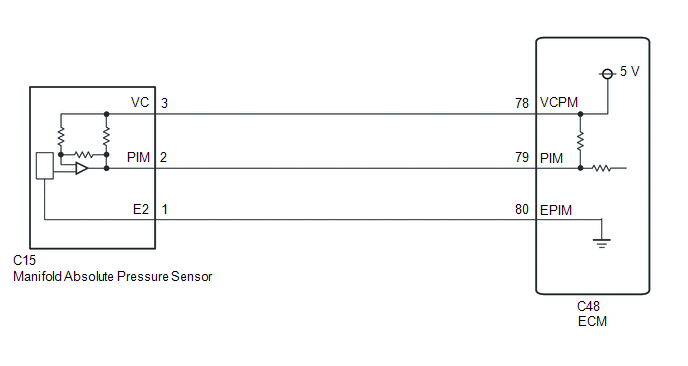
The manifold absolute pressure sensor detects the intake manifold pressure as a change in voltage. The ECM calculates the intake manifold pressure based on this voltage. The ECM calculates the EGR valve assembly and purge VSV opening amount according to changes in the intake manifold pressure and also detects errors in the manifold absolute pressure sensor using these changes in pressure.
| DTC No. | Detection Item | DTC Detection Condition | Trouble Area | MIL | Memory |
|---|---|---|---|---|---|
| P0107 | Manifold Absolute Pressure / Barometric Pressure Circuit Low Input | The output voltage from the manifold absolute pressure sensor is less than 0.5 V for 0.5 seconds (1 trip detection logic). |
| Comes on | DTC stored |
| P0108 | Manifold Absolute Pressure / Barometric Pressure Circuit High Input | The output voltage from the manifold absolute pressure sensor is higher than 4.5 V for 0.5 seconds (1 trip detection logic). |
| Comes on | DTC stored |
HINT:
When any of these DTCs are output, check the manifold absolute pressure using the Techstream. Enter the following menus: Powertrain / Engine and ECT / Data List / Primary / MAP.
| Pressure Displayed | Malfunction |
|---|---|
| Approximately 0 kPa(abs) [0 mmHg(abs)] | |
| 130 kPa(abs) [975 mmHg(abs)] or higher |
|
MONITOR DESCRIPTION
The ECM monitors the manifold absolute pressure sensor voltage and uses this value to calculate the intake manifold pressure. When the sensor output voltage deviates from the normal operating range, the ECM interprets this as a malfunction in the manifold absolute pressure sensor and stores a DTC.
Example:
When the sensor output voltage is less than 0.5 V, or higher than 4.5 V for 0.5 seconds, the ECM stores a DTC.
MONITOR STRATEGY
| Related DTCs | P0107: Manifold absolute pressure sensor range check (low voltage) P0108: Manifold absolute pressure sensor range check (high voltage) |
| Required Sensors/Components (Main) | Manifold absolute pressure sensor |
| Required Sensors/Components (Related) | - |
| Frequency of Operation | Continuous |
| Duration | 0.5 seconds |
| MIL Operation | Immediate |
| Sequence of Operation | None |
TYPICAL ENABLING CONDITIONS
| Monitor runs whenever the following DTCs are not stored | None |
| All of the following conditions are met | - |
| Auxiliary battery voltage | 8 V or higher |
| Power switch | On (IG) |
| Time after power switch off to on (IG) | 0.5 seconds or more |
TYPICAL MALFUNCTION THRESHOLDS
P0107| Manifold absolute pressure sensor voltage | Less than 0.5 V |
| Manifold absolute pressure sensor voltage | Higher than 4.5 V |
COMPONENT OPERATING RANGE
| Manifold absolute pressure sensor voltage | 0.5 to 4.5 V |
CONFIRMATION DRIVING PATTERN
- Connect the Techstream to the DLC3.
- Turn the power switch on (IG) and turn the Techstream on.
- Clear the DTCs (even if no DTCs are stored, perform the clear DTC procedure).
- Turn the power switch off and wait for at least 30 seconds.
- Turn the power switch on (IG) and turn the Techstream on.
-
Put the engine in inspection mode (maintenance mode).
Click here
.gif)
- Start the engine and wait 5 seconds or more.
- Enter the following menus: Powertrain / Engine and ECT / Trouble Codes.
-
Read the pending DTCs.
HINT:
- If a pending DTC is output, the system is malfunctioning.
- If a pending DTC is not output, perform the following procedure.
- Enter the following menus: Powertrain / Engine and ECT / Utility / All Readiness.
- Input the DTC: P0107 or P0108.
-
Check the DTC judgment result.
Techstream Display
Description
NORMAL
- DTC judgment completed
- System normal
ABNORMAL
- DTC judgment completed
- System abnormal
INCOMPLETE
- DTC judgment not completed
- Perform driving pattern after confirming DTC enabling conditions
N/A
- Unable to perform DTC judgment
- Number of DTCs which do not fulfill DTC preconditions has reached ECU memory limit
HINT:
- If the judgment result shows NORMAL, the system is normal.
- If the judgment result shows ABNORMAL, the system has a malfunction.
-
If the judgment result shows INCOMPLETE or N/A and no pending DTC is output, perform a universal trip and check for permanent DTCs.
Click here
HINT:
- If a permanent DTC is output, the system is malfunctioning.
- If no permanent DTC is output, the system is normal.
WIRING DIAGRAM
CAUTION / NOTICE / HINT
HINT:
Read freeze frame data using the Techstream. The ECM records vehicle and driving condition information as freeze frame data the moment a DTC is stored. When troubleshooting, freeze frame data can help determine if the vehicle was moving or stationary, if the engine was warmed up or not, if the air fuel ratio was lean or rich, and other data from the time the malfunction occurred.
PROCEDURE
| 1. | READ VALUE USING TECHSTREAM (MAP) |
(a) Connect the Techstream to the DLC3.
(b) Turn the power switch on (IG).
(c) Turn the Techstream on.
(d) Enter the following menus: Powertrain / Engine and ECT / Data List / Primary / MAP.
Powertrain > Engine and ECT > Data List| Tester Display |
|---|
| MAP |
(e) Read the MAP value.
OK:
Same value as the actual atmospheric pressure.
HINT:
- Standard atmospheric pressure is 101 kPa(abs) [758 mmHg(abs)]. For every 100 m (328 ft.) increase in altitude, atmospheric pressure drops by approximately 1 kPa (7.5 mmHg). The pressure also varies due to the weather (high atmospheric pressure, low atmospheric pressure).
- Check "Atmosphere Pressure" in the Data List.
| OK | .gif) | CHECK FOR INTERMITTENT PROBLEMS |
|
.gif)
| 2. | CHECK TERMINAL VOLTAGE (MANIFOLD ABSOLUTE PRESSURE SENSOR) |
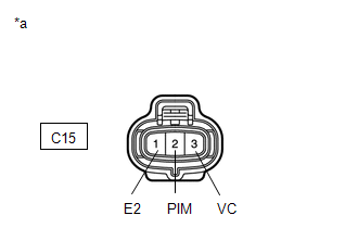
| (a) Disconnect the manifold absolute pressure sensor connector. |
|
(b) Turn the power switch on (IG).
(c) Measure the voltage according to the value(s) in the table below.
Standard Voltage:
| Tester Connection | Condition | Specified Condition |
|---|---|---|
| C15-3 (VC) - C15-1 (E2) | Power switch on (IG) | 4.75 to 5.25 V |
| C15-2 (PIM) - C15-1 (E2) | Power switch on (IG) | 3.0 to 5.0 V |
| NG | | GO TO STEP 5 |
|
| 3. | REPLACE MANIFOLD ABSOLUTE PRESSURE SENSOR |
(a) Replace the manifold absolute pressure sensor.
Click here
|
| 4. | CHECK WHETHER DTC OUTPUT RECURS (P0107 OR P0108) |
(a) Connect the Techstream to the DLC3.
(b) Turn the power switch on (IG).
(c) Turn the Techstream on.
(d) Clear the DTC.
Click here
(e) Turn the power switch off and wait for at least 30 seconds.
(f) Turn the power switch on (IG).
(g) Turn the Techstream on.
(h) Drive the vehicle in accordance with the driving pattern described in the Confirmation Driving Pattern.
(i) Enter the following menus: Powertrain / Engine and ECT / Trouble Codes.
(j) Read the DTCs.
Powertrain > Engine and ECT > Trouble Codes| Result | Proceed to |
|---|---|
| DTCs are not output | A |
| DTC P0107 or P0108 is output | B |
| A | | END |
| B | | REPLACE ECM |
| 5. | CHECK HARNESS AND CONNECTOR (MANIFOLD ABSOLUTE PRESSURE SENSOR - ECM) |
(a) Disconnect the manifold absolute pressure sensor connector.
(b) Disconnect the ECM connector.
(c) Measure the resistance according to the value(s) in the table below.
Standard Resistance:
| Tester Connection | Condition | Specified Condition |
|---|---|---|
| C15-3 (VC) - C48-78 (VCPM) | Always | Below 1 Ω |
| C15-1 (E2) - C48-80 (EPIM) | Always | Below 1 Ω |
| C15-2 (PIM) - C48-79 (PIM) | Always | Below 1 Ω |
| C15-3 (VC) or C48-78 (VCPM) - Body ground | Always | 10 kΩ or higher |
| C15-2 (PIM) or C48-79 (PIM) - Body ground | Always | 10 kΩ or higher |
| OK | | REPLACE ECM |
| NG | | REPAIR OR REPLACE HARNESS OR CONNECTOR |
READ NEXT:
 Intake Air Temperature Sensor 1 Circuit Range / Performance (P0111)
DESCRIPTION Refer to DTC P0112. Click here DTC No. Detection Item DTC Detection Condition Trouble Area MIL Memory P0111 Intake Air Temperature Sensor 1 Circuit Range / Performance
Intake Air Temperature Circuit Low Input (P0112,P0113)
DESCRIPTION The intake air temperature sensor, mounted on the mass air flow meter sub-assembly, monitors the intake air temperature. The intake air temperature sensor has a built-in thermistor with a
Engine Coolant Temperature Circuit (P0115,P0117,P0118)
DESCRIPTION A thermistor, whose resistance value varies according to the engine coolant temperature, is built into the engine coolant temperature sensor. The structure of the sensor and its connection
SEE MORE:
CAN Communication Failure (Message Registry) (U1000)
DESCRIPTION This DTC is output when an internal malfunction of the CAN communication-related ECU is stored. DTC No. Detection Item DTC Detection Condition Trouble Area U1000 CAN Communication Failure (Message Registry) A headlight ECU sub-assembly LH CAN communication function malfu
Window Glass Antenna Wire
On-vehicle InspectionON-VEHICLE INSPECTION PROCEDURE 1. INSPECT WINDOW GLASS ANTENNA WIRE (a) Check for continuity of the antenna. HINT: Check for continuity at the center of each antenna wire as shown in the illustration. NOTICE:
When cleaning the quarter window assembly, wipe it in the di
© 2016-2026 Copyright www.lexunx.com
