Lexus NX: Removal
REMOVAL
CAUTION / NOTICE / HINT
HINT:
- Use the same procedure for the RH and LH sides.
- The procedure listed below is for the LH side.
PROCEDURE
1. REMOVE REAR WHEEL
Click here .gif)
2. REMOVE REAR SUSPENSION ARM COVER LH
Click here
3. REMOVE REAR HEIGHT CONTROL SENSOR SUB-ASSEMBLY LH
Click here
4. REMOVE REAR STABILIZER LINK ASSEMBLY LH
Click here
5. LOOSEN REAR NO. 2 SUSPENSION ARM ASSEMBLY LH
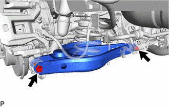
(a) Loosen the 2 bolts of the suspension arm.
NOTICE:
- Do not remove the bolts and nuts, only loosen them.
- Since a stopper nut is used, loosen the bolt.
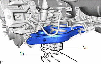
6. REMOVE REAR COIL SPRING LH
| (a) Support the No. 2 suspension arm LH with a jack. NOTICE: Place a wooden or rubber block between the jack and arm. |
|
| (b) Remove the bolt located on the rear axle carrier of the rear No. 2 suspension arm. |
|
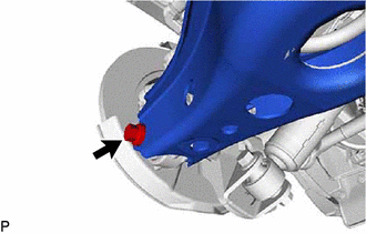
(c) Lower the jack gradually to remove the rear coil spring together with the rear upper coil spring insulator.
7. REMOVE REAR UPPER COIL SPRING INSULATOR LH
(a) Remove the rear upper coil spring insulator from the rear coil spring.
8. REMOVE REAR LOWER COIL SPRING INSULATOR LH
(a) Remove the rear lower coil spring insulator from the rear No. 2 suspension arm.
READ NEXT:
 Installation
INSTALLATION CAUTION / NOTICE / HINT HINT:
Use the same procedure for the RH and LH sides.
The procedure listed below is for the LH side.
PROCEDURE 1. INSTALL REAR UPPER COIL SPRING INSULATOR
Components
COMPONENTS ILLUSTRATION *A w/ AVS - - *1 REAR NO. 1 SUSPENSION ARM ASSEMBLY LH *2 REAR SHOCK ABSORBER ASSEMBLY LH *3 REAR SUSPENSION TOE ADJUST CAM SUB-ASSEMBLY *4 NO. 2
SEE MORE:
Open in Outer Mirror Indicator(Slave) (C1AB5)
DESCRIPTION This DTC is stored when the blind spot monitor sensor RH detects an open in the outer rear view mirror indicator RH. DTC No. Detection Item DTC Detection Condition Trouble Area Note C1AB5 Open in Outer Mirror Indicator(Slave) Both of the following conditions are met:
Adjustment (sequential Recognition)
ADJUSTMENT (SEQUENTIAL RECOGNITION) CAUTION / NOTICE / HINT NOTICE: Make sure to read Before Starting Adjustment before proceeding with work. Click here PROCEDURE 1. SECURE APPROPRIATE AREA FOR PERFORMING LEARNING (a) Park the vehicle on a level surface. HINT:
Make sure that the target recog
