- Target steering angle signal
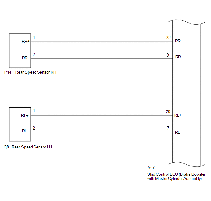
- Wheel speed signal
- Vehicle speed signal
Lexus NX: System Diagram
SYSTEM DIAGRAM
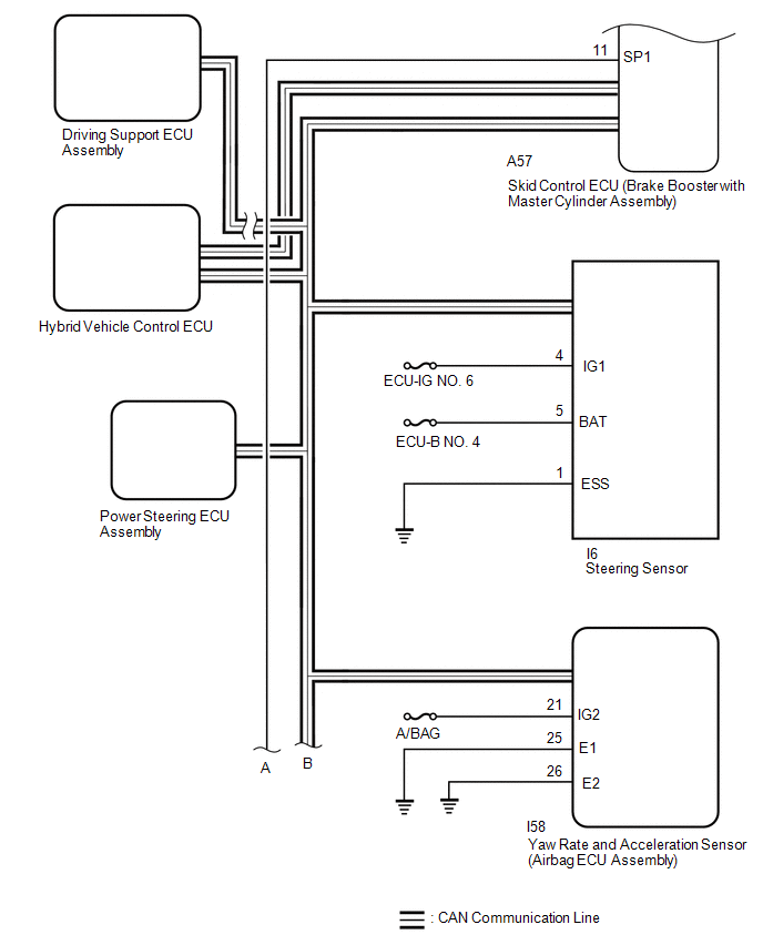
| Transmitting ECU (Transmitter) | Receiving ECU | Signal | Communication Method |
|---|---|---|---|
| Skid control ECU (Brake booster with master cylinder assembly) | Power steering ECU assembly | | CAN communication line |
| Main body ECU (Multiplex network body ECU) | Skid control ECU (Brake booster with master cylinder assembly) |
| CAN communication line |
| Skid control ECU (Brake booster with master cylinder assembly) | Hybrid vehicle control ECU |
| CAN communication line |
| Hybrid vehicle control ECU | Skid control ECU (Brake booster with master cylinder assembly) |
| CAN communication line |
| Skid control ECU (Brake booster with master cylinder assembly) | Steering sensor | Steering sensor request signal | CAN communication line |
| Steering sensor | Skid control ECU (Brake booster with master cylinder assembly) | Steering sensor signal | CAN communication line |
| Skid control ECU (Brake booster with master cylinder assembly) | Yaw rate and acceleration sensor (Airbag ECU assembly) | Yaw rate and acceleration request signal | CAN communication line |
| Yaw rate and acceleration sensor (Airbag ECU assembly) | Skid control ECU (Brake booster with master cylinder assembly) | Yaw rate and acceleration signal | CAN communication line |
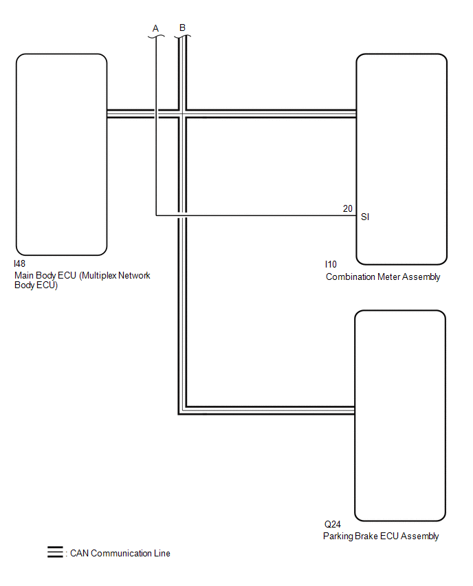
| Skid control ECU (Brake booster with master cylinder assembly) | Parking brake ECU assembly |
| CAN communication line |
| Parking brake ECU assembly | Skid control ECU (Brake booster with master cylinder assembly) |
| CAN communication line |
| Skid control ECU (Brake booster with master cylinder assembly) | Combination meter assembly |
| CAN communication line |
READ NEXT:
 System Description
SYSTEM DESCRIPTION FUNCTION DESCRIPTION (a) Electronically Controlled Brake System (1) Upon receiving signals from the skid control ECU (brake booster with master cylinder assembly), this system effec
How To Proceed With Troubleshooting
CAUTION / NOTICE / HINT HINT: *: Use the Techstream. PROCEDURE 1. VEHICLE BROUGHT TO WORKSHOP
NEXT 2. CUSTOMER PROBLEM ANALYSIS (a) Interview the customer and confir
Check For Intermittent Problems
CHECK FOR INTERMITTENT PROBLEMS CHECK FOR INTERMITTENT PROBLEMS HINT: A momentary interruption (open circuit) in the connectors and/or wire harnesses between the sensors and ECUs can be detected using
SEE MORE:
System Description
SYSTEM DESCRIPTION SYSTEM DESCRIPTION (a) The electric parking brake system electronically controls the parking brake lock and release operations using actuators. The main functions are as follows: Functions when vehicle stopped
When the electric parking brake switch (integration control and pane
Dtc Check / Clear
DTC CHECK / CLEAR CHECK DTC (a) Check main body ECU (multiplex network body ECU) (1) Connect the Techstream to the DLC3. (2) Turn the power switch on (IG). (3) Turn the Techstream on. (4) Enter the following menus: Body Electrical / Main Body / Trouble Codes. (5) Check for DTCs. Body Electrical >
© 2016-2026 Copyright www.lexunx.com
