Lexus NX: Check Mode Procedure
CHECK MODE PROCEDURE
HINT:
Compared to normal mode, check mode is more sensitive to malfunctions. Therefore, check mode can detect malfunctions that cannot be detected in normal mode.
NOTICE:
All the stored DTCs and freeze frame data are cleared if: 1) the ECM is changed from normal mode to check mode or vice versa; or 2) the power switch is turned from on (IG) to ACC or off while in check mode. Before changing modes, always check and note any DTCs and freeze frame data.
CHECK MODE PROCEDURE
(a) Check and ensure the following conditions:
(1) Auxiliary battery voltage is 11 V or higher.
(2) Throttle valve is fully closed.
(3) Shift lever is in P or N.
(4) A/C switch is off.
(b) Turn the power switch off.
(c) Connect the Techstream to the DLC3.
(d) Turn the power switch on (IG).
(e) Turn the Techstream on.
(f) Enter the following menus: Powertrain / Engine and ECT / Utility / Check Mode.
Powertrain > Engine and ECT > Utility| Tester Display |
|---|
| Check Mode |
(g) Switch the ECM from normal mode to check mode.
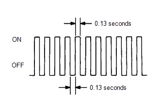
(h) Check that the MIL flashes as shown in the illustration.
(i) Turn the power switch on (READY).
(j) Check that the MIL turns off.
(k) Simulate the conditions of the malfunction described by the customer.
(l) Check DTCs and freeze frame data using the Techstream.
READ NEXT:
 Fail-safe Chart
FAIL-SAFE CHART If any of the following DTCs are stored, the ECM enters fail-safe mode to allow the vehicle to be driven temporarily or stops fuel injection. DTC Code Component Fail-Safe Operat
Data List / Active Test
DATA LIST / ACTIVE TEST DATA LIST HINT: Using the Techstream to read the Data List allows the values or states of switches, sensors, actuators and other items to be read without removing any parts. Th
Diagnostic Trouble Code Chart
DIAGNOSTIC TROUBLE CODE CHART SFI System DTC No. Detection Item MIL Memory Link P0010 Camshaft Position "A" Actuator Circuit (Bank 1) Comes on DTC stored P0011 Camshaft
SEE MORE:
Problem Symptoms Table
PROBLEM SYMPTOMS TABLE HINT: Use the table below to help determine the cause of problem symptoms. If multiple suspected areas are listed, the potential causes of the symptoms are listed in order of probability in the "Suspected Area" column of the table. Check each symptom by checking the suspected
Installation
INSTALLATION PROCEDURE 1. INSTALL TRANSMISSION OIL COOLER ASSEMBLY (a) Insert the stud bolts E through the transmission oil cooler assembly. *a Torque Wrench Fulcrum Length (b) Temporarily install the transmission oil cooler assembly and a new gasket with the flare nut B a
