- DTC judgment completed
- System normal
Lexus NX: System Voltage (P0560)
Lexus NX Service Manual / Engine & Hybrid System / 2ar-fxe (engine Control) / Sfi System / System Voltage (P0560)
MONITOR DESCRIPTION
The auxiliary battery supplies electricity to the ECM even when the power switch is off. This power allows the ECM to store data such as DTC history, freeze frame data and fuel trim values. If the auxiliary battery voltage falls below a minimum level, the memory is cleared and the ECM determines that there is a malfunction in the power supply circuit. The ECM will illuminate the MIL and store this DTC.
| DTC No. | Detection Item | DTC Detection Condition | Trouble Area | MIL | Memory |
|---|---|---|---|---|---|
| P0560 | System Voltage | An open in the ECM back up power source circuit (1 trip detection logic). |
| Comes on | DTC stored |
HINT:
If DTC P0560 is stored, the ECM does not store other DTCs or the data stored in the ECM is partially cleared.
MONITOR STRATEGY
| Related DTCs | P0560: System voltage range check |
| Required Sensors/Components (Main) | ECM |
| Required Sensors/Components (Related) | - |
| Frequency of Operation | Continuous |
| Duration | 3 seconds |
| MIL Operation | Immediate |
| Sequence of Operation | None |
TYPICAL ENABLING CONDITIONS
| Monitor runs whenever the following DTCs are not stored | None |
TYPICAL MALFUNCTION THRESHOLDS
| Both of the following conditions are met | - |
| Stand-by RAM | Initialized |
| Continuous auxiliary battery voltage | Less than 3.5 V |
CONFIRMATION DRIVING PATTERN
- Connect the Techstream to the DLC3.
- Turn the power switch on (IG) and turn the Techstream on.
- Clear the DTCs (even if no DTCs are stored, perform the clear DTC procedure).
- Turn the power switch off and wait for at least 30 seconds.
- Turn the power switch on (IG) and turn the Techstream on.
- Wait 5 seconds or more.
- Enter the following menus: Powertrain / Engine and ECT / Trouble Codes.
-
Read the pending DTCs.
HINT:
- If a pending DTC is output, the system is malfunctioning.
- If a pending DTC is not output, perform the following procedure.
- Enter the following menus: Powertrain / Engine and ECT / Utility / All Readiness.
- Input the DTC: P0560.
-
Check the DTC judgment result.
Techstream Display
Description
NORMAL
ABNORMAL
- DTC judgment completed
- System abnormal
INCOMPLETE
- DTC judgment not completed
- Perform driving pattern after confirming DTC enabling conditions
N/A
- Unable to perform DTC judgment
- Number of DTCs which do not fulfill DTC preconditions has reached ECU memory limit
HINT:
- If the judgment result shows NORMAL, the system is normal.
- If the judgment result shows ABNORMAL, the system has a malfunction.
-
If the judgment result is INCOMPLETE or N/A and no pending DTC is output, perform a universal trip and check for permanent DTCs.
Click here
.gif)
HINT:
- If a permanent DTC is output, the system is malfunctioning.
- If no permanent DTC is output, the system is normal.
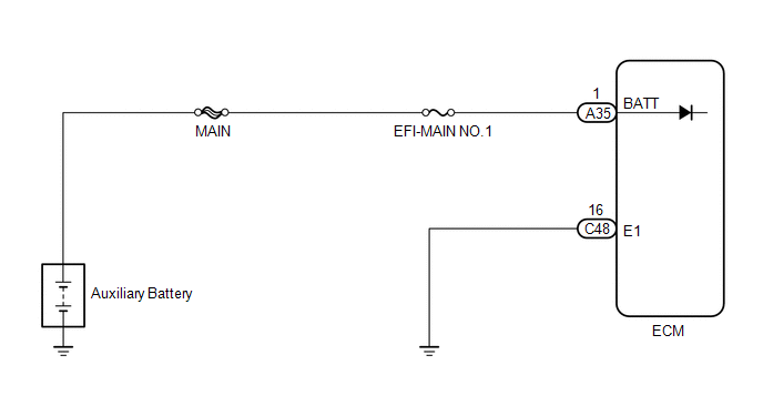
WIRING DIAGRAM
CAUTION / NOTICE / HINT
NOTICE:
- Inspect the fuses for circuits related to this system before performing the following procedure.
-
After the power switch is turned off, there may be a waiting time before disconnecting the negative (-) auxiliary battery terminal.
Click here
-
When disconnecting and reconnecting the auxiliary battery.
Click here
HINT:
When disconnecting and reconnecting the auxiliary battery, there is an automatic learning function that completes learning when the respective system is used.
Click here
HINT:
Read freeze frame data using the Techstream. The ECM records vehicle and driving condition information as freeze frame data the moment a DTC is stored. When troubleshooting, freeze frame data can help determine if the vehicle was moving or stationary, if the engine was warmed up or not, if the air fuel ratio was lean or rich, and other data from the time the malfunction occurred.
PROCEDURE
| 1. | INSPECT AUXILIARY BATTERY |
(a) Inspect the auxiliary battery.
Click here
OK:
Auxiliary battery is not depleted
| NG | .gif) | CHARGE OR REPLACE AUXILIARY BATTERY |
|
.gif)
| 2. | CHECK AUXILIARY BATTERY TERMINAL |
(a) Check that the auxiliary battery terminals are not loose or corroded.
Click here
OK:
Auxiliary battery terminals are not loose or corroded.
| NG | | REPAIR OR REPLACE AUXILIARY BATTERY TERMINAL |
|
| 3. | CHECK TERMINAL VOLTAGE (POWER SOURCE OF ECM) |
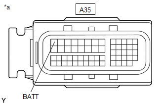
| *a | Front view of wire harness connector (to ECM) |
(a) Disconnect the ECM connector.
(b) Measure the voltage according to the value(s) in the table below.
Standard Voltage:
| Tester Connection | Condition | Specified Condition |
|---|---|---|
| A35-1 (BATT) - Body ground | Always | 11 to 16 V |
| NG | | REPAIR OR REPLACE HARNESS OR CONNECTOR (AUXILIARY BATTERY - ECM) |
|
| 4. | CHECK WHETHER DTC OUTPUT RECURS (DTC P0560) |
(a) Connect the Techstream to the DLC3.
(b) Turn the power switch on (IG).
(c) Turn the Techstream on.
(d) Clear the DTCs.
Click here
(e) Turn the power switch off and wait for at least 30 seconds.
(f) Turn the power switch on (IG) and turn the Techstream on.
(g) Wait 5 seconds or more.
(h) Enter the following menus: Powertrain / Engine and ECT / Trouble Codes.
(i) Read the DTCs.
Powertrain > Engine and ECT > Trouble Codes| Result | Proceed to |
|---|---|
| DTC P0560 is output | A |
| DTCs are not output | B |
| A | | REPLACE ECM |
| B | | CHECK FOR INTERMITTENT PROBLEMS |
READ NEXT:
 Random Access Memory (RAM) (P0604)
MONITOR DESCRIPTION The ECM continuously monitors its internal memory status. This self-check ensures that the ECM is functioning properly. The ECM memory status is diagnosed by internal mirroring of
ECM / PCM Processor (P0606)
MONITOR DESCRIPTION The ECM continuously monitors its main and sub CPUs. This self-check ensures that the ECM is functioning properly. If outputs from these CPUs are different and deviate from the sta
Control Module Performance (P0607)
MONITOR DESCRIPTION The ECM continuously monitors its internal processors (CPUs) and heated oxygen sensor transistors. This self-check ensures that the ECM functioning properly. DTC No. Detection
SEE MORE:
If you have a flat tire
Your vehicle is equipped with a
spare tire. The flat tire can be
replaced with the spare tire.
WARNING
■If you have a flat tire
Do not continue driving with a flat tire.
Driving even a short distance with a flat
tire can damage the tire and the wheel
beyond repair, which could result in
Inspection
INSPECTION PROCEDURE 1. INSPECT BACK DOOR LOCK ASSEMBLY (BACK DOOR COURTESY SWITCH) (a) w/o Power Back Door: (1) Move the back door lock assembly to the lock position. *1 Latch *a Component without harness connected (Back Door Lock Assembly (Back Door Courtesy Switch)) *b
© 2016-2026 Copyright www.lexunx.com
