Lexus NX: Inspection
INSPECTION
PROCEDURE
1. INSPECT BACK DOOR LOCK ASSEMBLY (BACK DOOR COURTESY SWITCH)
(a) w/o Power Back Door:
| (1) Move the back door lock assembly to the lock position. |
|
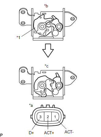
(2) Measure the resistance according to the value(s) in the table below.
Standard Resistance:
| Tester Connection | Condition | Specified Condition |
|---|---|---|
| 1 (ACT-) - 3 (D+) | Lock | 10 kΩ or higher |
(3) Apply battery voltage to the door lock motor and check the operation of the door lock motor.
OK:
| Tester Connection | Condition | Specified Condition |
|---|---|---|
| 2 (ACT+) - 1 (ACT-) | Battery positive (+) → 2 (ACT+) Battery negative (-) → 1 (ACT-) | Unlock |
(4) Measure the resistance according to the value(s) in the table below.
Standard Resistance:
| Tester Connection | Condition | Specified Condition |
|---|---|---|
| 1 (ACT-) - 3 (D+) | Unlock | Below 1 Ω |
(b) w/ Power Back Door:
| (1) Apply battery voltage to the door lock motor and check the operation of the door lock motor. OK:
|
|
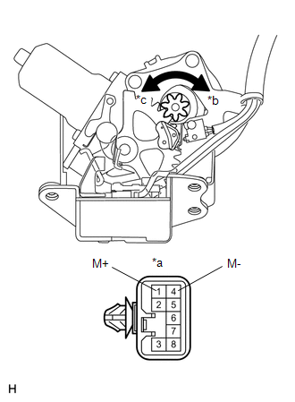
| (2) Measure the resistance according to the value(s) in the table below. Standard Resistance:
If the result is not as specified, replace the back door lock assembly (back door courtesy switch). |
|
READ NEXT:
 Installation
INSTALLATION PROCEDURE 1. INSTALL BACK DOOR LOCK ASSEMBLY (BACK DOOR COURTESY SWITCH) HINT:
When installing a new back door lock assembly (back door courtesy switch), if there is a rope on the asse
Components
COMPONENTS ILLUSTRATION *A w/ Wireless Charger *B w/o Wireless Charger *1 CONSOLE BOX ASSEMBLY *2 CONSOLE BOX ILLUMINATION LIGHT ASSEMBLY *3 CONSOLE COMPARTMENT DOOR SUB-ASSE
SEE MORE:
Installation
INSTALLATION PROCEDURE 1. INSTALL CABLE SUPPORT BRACKET (a) Install the cable support bracket to the rear suspension member sub-assembly with the 2 bolts. Torque: 6.0 N·m {61 kgf·cm, 53 in·lbf} 2. INSTALL REAR STABILIZER SUPPORT BRACKET LH (a) Install the rear stabilizer support bracket LH to th
Seat Belt Tension Reducer System
Parts LocationPARTS LOCATION ILLUSTRATION *A w/ Memory - - *1 FRONT SEAT INNER BELT ASSEMBLY RH *2 FRONT SEAT INNER BELT ASSEMBLY LH *3 FRONT SEAT OUTER BELT ASSEMBLY RH *4 FRONT SEAT OUTER BELT ASSEMBLY LH *5 FRONT POWER SEAT SWITCH LH *6 INSTRUMENT PANEL JU
