Lexus NX: Telematics Transceiver Disconnected (B15DB)
DESCRIPTION
If the radio receiver assembly cannot detect the DCM (telematics transceiver) for a certain period of time (90 seconds) after the power switch is turned on (IG) and the radio receiver assembly confirms that the information is missing by checking past DCM (telematics transceiver) recognition information (registered information), this DTC will be stored.
HINT:
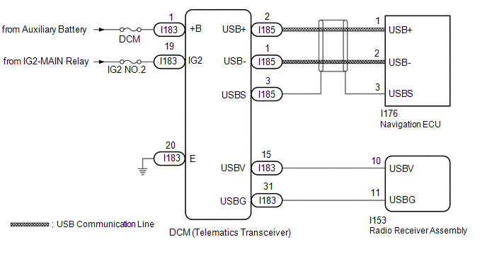
The LEXUS Enform system uses USB communication between devices. If an open, short, short to +B or short to ground occurs in the USB circuit, communication is interrupted and the LEXUS Enform system will not operate normally.
| DTC No. | Detection Item | DTC Detection Condition | Trouble Area |
|---|---|---|---|
| B15DB | Telematics Transceiver Disconnected | DCM (telematics transceiver) disconnected |
|
HINT:
This DTC may be stored due to environmental reasons such as electrical noise or interference.
WIRING DIAGRAM
CAUTION / NOTICE / HINT
NOTICE:
- Inspect the fuses for circuits related to this system before performing the following procedure.
- When replacing the DCM (telematics transceiver), make sure to replace it with a new one.
-
When replacing the radio receiver assembly or navigation ECU, always replace it with a new one.
If a radio receiver assembly or navigation ECU which was installed to another vehicle is used, the following may occur:
- A communication malfunction DTC may be stored.
- The radio receiver assembly or navigation ECU may not operate normally.
HINT:
Depending on the parts that are replaced during vehicle inspection or maintenance, performing initialization, registration or calibration may be needed. Refer to Precaution for Navigation System.
Click here .gif)
PROCEDURE
| 1. | CHECK DTC |
(a) Clear the DTCs.
Click here
(b) Turn the power switch off.
(c) Turn the power switch on (IG) and wait for 90 seconds.
(d) Recheck for DTCs and check that no DTCs are output.
Click here
OK:
No DTCs are output.
| OK | .gif) | USE SIMULATION METHOD TO CHECK |
|
.gif)
| 2. | CHECK HARNESS AND CONNECTOR (DCM [TELEMATICS TRANSCEIVER] - BATTERY AND BODY GROUND) |
| (a) Disconnect the DCM (telematics transceiver) connector. |
|
(b) Measure the resistance according to the value(s) in the table below.
Standard Resistance:
| Tester Connection | Condition | Specified Condition |
|---|---|---|
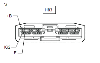
| I183-20 (E) - Body ground | Always | Below 1 Ω |
(c) Measure the voltage according to the value(s) in the table below.
Standard Voltage:
| Tester Connection | Switch Condition | Specified Condition |
|---|---|---|
| I183-1 (+B) - Body ground | Power switch off | 11 to 14 V |
| I183-19 (IG2) - Body ground | Power switch on (IG) | 11 to 14 V |
| NG | | REPAIR OR REPLACE HARNESS OR CONNECTOR |
|
| 3. | CHECK HARNESS AND CONNECTOR (RADIO RECEIVER ASSEMBLY - DCM [TELEMATICS TRANSCEIVER]) |
(a) Disconnect the I153 radio receiver assembly connector.
(b) Disconnect the I183 DCM (telematics transceiver) connector.
(c) Measure the resistance according to the value(s) in the table below.
Standard Resistance:
| Tester Connection | Condition | Specified Condition |
|---|---|---|
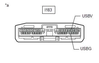
| I153-10 (USBV) - I183-15 (USBV) | Always | Below 1 Ω |
| I153-11 (USBG) - I183-31 (USBG) | Always | Below 1 Ω |
| I153-10 (USBV) - Body ground | Always | 10 kΩ or higher |
| I153-11 (USBG) - Body ground | Always | 10 kΩ or higher |
| NG | | REPAIR OR REPLACE HARNESS OR CONNECTOR |
|
| 4. | CHECK RADIO RECEIVER ASSEMBLY (USBV, USBG) |
(a) Disconnect the DCM (telematics transceiver) connector.
| (b) Measure the resistance according to the value(s) in the table below. Standard Resistance:
|
|
(c) Measure the voltage according to the value(s) in the table below.
Standard Voltage:
| Tester Connection | Switch Condition | Specified Condition |
|---|---|---|
| I183-15 (USBV) - I183-31 (USBG) | Power switch on (IG) | 4.75 to 5.25 V |
| NG | | REPLACE RADIO RECEIVER ASSEMBLY |
|
| 5. | CHECK HARNESS AND CONNECTOR (DCM [TELEMATICS TRANSCEIVER] - NAVIGATION ECU) |
| (a) Disconnect the I185 DCM (telematics transceiver) connector. |
|
(b) Disconnect the I176 navigation ECU connector.
(c) Measure the resistance according to the value(s) in the table below.
Standard Resistance:
| Tester Connection | Condition | Specified Condition |
|---|---|---|
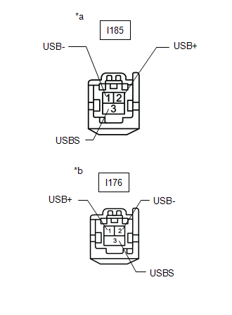
| I185-2 (USB+) - I176-1 (USB+) | Always | Below 1 Ω |
| I185-1 (USB-) - I176-2 (USB-) | Always | Below 1 Ω |
| I185-3 (USBS) - I176-3 (USBS) | Always | Below 1 Ω |
| I185-2 (USB+) - Body ground | Always | 10 kΩ or higher |
| I185-1 (USB-) - Body ground | Always | 10 kΩ or higher |
| I185-3 (USBS) - Body ground | Always | 10 kΩ or higher |
| NG | | REPAIR OR REPLACE HARNESS OR CONNECTOR |
|
| 6. | CHECK DCM (TELEMATICS TRANSCEIVER) |
(a) Replace the DCM (telematics transceiver) with a new one.
Click here
(b) Clear the DTCs.
Click here
(c) Turn the power switch off.
(d) Turn the power switch on (IG) and wait for 90 seconds.
(e) Recheck for DTCs and check that no DTCs are output.
Click here
OK:
No DTCs are output.
| OK | | END (DCM [TELEMATICS TRANSCEIVER] IS DEFECTIVE) |
|
| 7. | CHECK NAVIGATION ECU |
(a) Replace the navigation ECU with a new one.
Click here
(b) Clear the DTCs.
Click here
(c) Turn the power switch off.
(d) Turn the power switch on (IG) and wait for 90 seconds.
(e) Recheck for DTCs and check that no DTCs are output.
Click here
OK:
No DTCs are output.
| OK | | END (NAVIGATION ECU IS DEFECTIVE) |
| NG | | REPLACE RADIO RECEIVER ASSEMBLY |
READ NEXT:
 Air Conditioner ECU Vehicle Information Reading/Writing Processor Malfunction (B15F5)
DESCRIPTION This DTC is stored when items controlled by the air conditioning amplifier assembly cannot be customized via the navigation system vehicle customization screen. HINT: The air conditioning
Main Body ECU Vehicle Information Reading/Writing Process Malfunction (B15F6)
DESCRIPTION This DTC is stored when items controlled by the main body ECU (multiplex network body ECU) cannot be customized via the navigation system vehicle customization screen. HINT: The main body
Certification ECU Vehicle Information Reading/Writing Process Malfunction (B15F7)
DESCRIPTION This DTC is stored when items controlled by the certification ECU cannot be customized via the navigation system vehicle customization screen. HINT: The certification ECU controls the smar
SEE MORE:
Entry Interior Alarm does not Sound
DESCRIPTION The smart access system with push-button start (for Entry Function) uses the buzzer in the combination meter assembly (meter ECU) to perform various vehicle interior warnings. When the conditions of each warning are met, the certification ECU (smart key ECU assembly) sends a buzzer activ
Diagnosis System
DIAGNOSIS SYSTEM DIAGNOSIS FUNCTION (a) The front camera system does not have a notification function such as a warning light when a DTC is detected. When a malfunction occurs, it stores a DTC and sends it to the systems using the front camera system. The system receiving the malfunction information
