Lexus NX: MG-ECU Power Relay Intermittent Circuit (P324E-788)
DESCRIPTION
If the MG ECU, which is built into in the inverter with converter assembly, is reset due to a problem with the power source in the inverter, the hybrid vehicle control ECU will stored this DTC.
| DTC No. | Detection Item | DTC Detection Condition | Trouble Area | MIL | Warning Indicate |
|---|---|---|---|---|---|
| P324E-788 | MG-ECU Power Relay Intermittent Circuit | Error in reset signal from the inverter assembly power source IC: If internal power source voltage drops below the normal CPU operating voltage or the ROM/RAM is malfunctioning, the power source IC resets the MG ECU and stores this DTC. (1 trip detection logic) |
| Does not come on | Master Warning Light: Comes on |
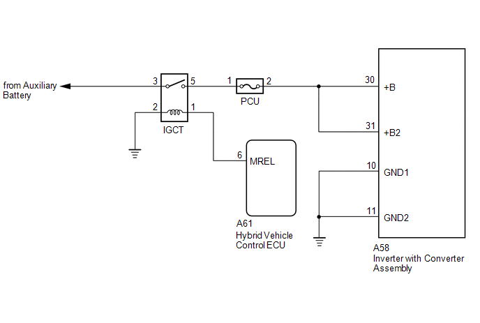
WIRING DIAGRAM
CAUTION / NOTICE / HINT
CAUTION:
- Before inspecting the high-voltage system or disconnecting the low voltage connector of the inverter with converter assembly, take safety precautions such as wearing insulated gloves and removing the service plug grip to prevent electrical shocks. After removing the service plug grip, put it in your pocket to prevent other technicians from accidentally reconnecting it while you are working on the high-voltage system.
-
After removing the service plug grip, wait for at least 10 minutes before touching any of the high-voltage connectors or terminals. After waiting for 10 minutes, check the voltage at the terminals in the inspection point in the inverter with converter assembly. The voltage should be 0 V before beginning work.
Click here
.gif)
HINT:
Waiting for at least 10 minutes is required to discharge the high-voltage capacitor inside the inverter with converter assembly.
NOTICE:
After turning the power switch off, waiting time may be required before disconnecting the cable from the negative (-) auxiliary battery terminal. Therefore, make sure to read the disconnecting the cable from the negative (-) auxiliary battery terminal notices before proceeding with work.
Click here
HINT:
After the repair, clear the DTCs and perform the following procedure to check that DTCs are not output.
- Turn the power switch on (IG) and wait for 5 seconds or more.
PROCEDURE
| 1. | CHECK DTC OUTPUT (HYBRID CONTROL) |
(a) Connect the Techstream to the DLC3.
(b) Turn the power switch on (IG).
(c) Enter the following menus: Powertrain / Hybrid Control / Trouble Codes.
(d) Check for DTCs.
Powertrain > Hybrid Control > Trouble Codes| Result | Proceed to |
|---|---|
| P324E-788 only is output or any DTCs other than U0110-159, 160, 656, 657 is also output. | A |
| U0110-159, 160, 656, 657 are also output. | B |
(e) Turn the power switch off.
| B | .gif) | GO TO DTC CHART (HYBRID CONTROL SYSTEM) |
|
.gif)
| 2. | CHECK CONNECTOR CONNECTION CONDITION (INVERTER WITH CONVERTER ASSEMBLY CONNECTOR) |
Click here
| Result | Proceed to |
|---|---|
| OK | A |
| NG (The connector is not connected securely.) | B |
| NG (The terminals are not making secure contact or are deformed, or water or foreign matter exists in the connector.) | C |
| B | | CONNECT SECURELY |
| C | | REPAIR OR REPLACE HARNESS OR CONNECTOR |
|
| 3. | CHECK HARNESS AND CONNECTOR (INVERTER WITH CONVERTER ASSEMBLY - IGCT RELAY) |
CAUTION:
Be sure to wear insulated gloves.
(a) Check that the service plug grip is not installed.
NOTICE:
After removing the service plug grip, do not turn the power switch on (READY), unless instructed by the repair manual because this may cause a malfunction.
(b) Disconnect the A58 inverter with converter assembly connector.
(c) Remove the IGCT relay from the No. 1 engine room relay block.
(d) Measure the resistance according to the value(s) in the table below.
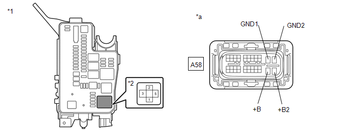
| *1 | No. 1 Engine Room Relay Block | *2 | IGCT Relay |
| *a | Front view of wire harness connector (to Inverter with Converter Assembly) | - | - |
Standard Resistance:
| Tester Connection | Condition | Specified Condition |
|---|---|---|
| A58-30 (+B) - 5 (IGCT relay) | Power switch off | Below 1 Ω |
| A58-31 (+B2) - 5 (IGCT relay) | Power switch off | Below 1 Ω |
| A58-10 (GND1) - Body ground | Power switch off | Below 1 Ω |
| A58-11 (GND2) - Body ground | Power switch off | Below 1 Ω |
(e) Install the IGCT relay.
(f) Reconnect the A58 inverter with converter assembly connector.
| OK | | REPLACE INVERTER WITH CONVERTER ASSEMBLY |
| NG | | REPAIR OR REPLACE HARNESS OR CONNECTOR |
READ NEXT:
 Lost Communication with ECM / PCM "A" (U0100-530,U0126-735,U0129-527,U0129-528,U0140-146,U0151-763,U0164-827,U1107-436)
DESCRIPTION The hybrid vehicle control ECU transmits and receives signals via CAN communication to and from the ECM, skid control ECU assembly, power steering ECU assembly, main body ECU, airbag ECU a
Lost Communication with Drive Motor Control Module "A" (U0110-159,U0110-656,U0110-657)
DESCRIPTION For a description of the inverter. Click here The MG ECU, which is built into in the inverter with converter assembly, controls motor (MG2) based on commands from the hybrid vehicle cont
Lost Communication with Drive Motor Control Module "A" (U0110-160)
DESCRIPTION The MG ECU, which is built into in the inverter with converter assembly, controls motor (MG2) based on commands from the hybrid vehicle control ECU. The motor generator control ECU (MG ECU
SEE MORE:
Transmission Control Switch Circuit
DESCRIPTION When the shift lever is in S, different ranges can be chosen using the floor shift sequential gate. WIRING DIAGRAM PROCEDURE 1. READ VALUE USING TECHSTREAM (SPORTS MODE) (a) Connect the Techstream to the DLC3. (b) Turn the power switch on (IG). (c) Enter the following menus: Po
Removal
REMOVAL PROCEDURE 1. REMOVE FRONT BUMPER ASSEMBLY Click here 2. REMOVE NO. 3 ENGINE ROOM WIRE Click here 3. REMOVE CLEARANCE LIGHT ASSEMBLY LH (a) for LED Type Side Turn Signal Light: Click here (b) for Bulb Type Side Turn Signal Light: Click here 4. REMOVE CLEARANCE LIGHT ASSEMBLY RH HINT:
