- Y26-1 (DS1) - Body ground
- Y26-3 (DS12) - Body ground
Lexus NX: Terminals Of Ecu
Lexus NX Service Manual / Vehicle Exterior / Door / Hatch / Power Back Door System / Terminals Of Ecu
TERMINALS OF ECU
CHECK MULTIPLEX NETWORK DOOR ECU
(a) Disconnect the Y26 and Y27 multiplex network door ECU connectors.
.png)
(b) Measure the voltage and resistance according to the value(s) in the table below.
| Terminal No. (Symbol) | Wiring Color | Terminal Description | Condition | Specified Condition |
|---|---|---|---|---|
| Y26-18 (IG) - Body ground | W - Body ground | IG power supply | Power switch on (IG) | 11 to 14 V |
| Power switch off | Below 1 V | |||
| Y26-20 (ECUB) - Body ground | W - Body ground | Auxiliary battery power supply | Power switch off | 11 to 14 V |
| Y27-1 (B) - Body ground | LA-W - Body ground | Auxiliary battery power supply | Power switch off | 11 to 14 V |
| Y27-10 (GND) - Body ground | W-B - Body ground | Body ground | Always | Below 1 Ω |
(c) Reconnect the Y26 and Y27 multiplex network door ECU connectors.
(d) Measure the voltage and waveform according to the value(s) in the table below.
| Terminal No. (Symbol) | Wiring Color | Terminal Description | Condition | Specified Condition |
|---|---|---|---|---|
| *: w/ Hands Free Power Back Door | ||||
| Y26-1 (DS1) - Body ground | L - Body ground | Power back door unit assembly LH (door sensor) signal | Power back door not operating | 7 V or higher |
| Power back door operating | Pulse generation (See waveform 1) | |||
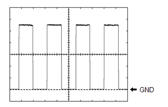
| Y26-2 (DS2) - Body ground | R - Body ground | Power back door unit assembly LH (door sensor) signal | Power back door not operating | 7 V or higher |
| Power back door operating | Pulse generation (See waveform 2) | |||
| Y26-3 (DS12) - Body ground | LG - Body ground | Power back door unit assembly RH (door sensor) signal | Power back door not operating | 7 V or higher |
| Power back door operating | Pulse generation (See waveform 1) | |||
| Y26-4 (DS22) - Body ground | B - Body ground | Power back door unit assembly RH (door sensor) signal | Power back door not operating | 7 V or higher |
| Power back door operating | Pulse generation (See waveform 2) | |||
| Y26-5 (DSV2) - Body ground | BE - Body ground | Power back door unit assembly RH (door sensor) power supply | Always | 7 V or higher |
| Y26-6 (OSR) - Y26-24 (OSE) | SB - GR | Power back door sensor assembly RH signal | Power back door sensor assembly RH not pressed | 4 to 6 V |
| Power back door sensor assembly RH pressed | Below 1 V | |||
| Y26-8 (BDDN) - Body ground | LG - Body ground | Back door control switch signal | Back door control switch on | Below 1 V |
| Back door control switch off | Pulse generation | |||
| Y26-10 (CLSW) - Body ground | V - Body ground | Door control switch signal | Door control switch on | Below 1 V |
| Door control switch off | 11 to 14 V | |||
| Y26-14 (KSIN) - Body ground* | W - Body ground | Kick detection signal | Power switch on (IG), kick door control sensor not detecting a foot → detecting a foot | Pulse generation (See waveform 3) |
| Y26-16 (BZR+) - Body ground | V - Body ground | Wireless door lock buzzer signal | Power back door warning buzzer sounding | Pulse generation |
| Power back door warning buzzer not sounding | Below 1 V | |||
| Y26-19 (DSG2) - Body ground | V - Body ground | Power back door unit assembly RH (door sensor) ground | Always | Below 1 V |
| Y26-21 (DSG) - Body ground | GR - Body ground | Power back door unit assembly LH (door sensor) ground | Always | Below 1 V |
| Y26-25 (DSV) - Body ground | G - Body ground | Power back door unit assembly LH (door sensor) power supply | Always | 7 V or higher |
| Y26-26 (OSL) - Y26-24 (OSE) | P - GR | Power back door sensor assembly LH signal | Power back door sensor assembly LH not pressed | 4 to 6 V |
| Power back door sensor assembly LH pressed | Below 1 V | |||
| Y27-4 (DC+) - Y27-3 (DC-) | LA-BR - LA-R | Back door lock assembly (back door lock motor) circuit | Back door lock motor operating | 11 to 14 V |
| Back door lock motor not operating | Below 1 V | |||
(1) Using an oscilloscope, check waveform 1.
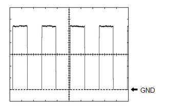 Waveform 1 (Reference)
 | Item | Condition |
|---|---|
| Tester Connection | |
| Tool setting | 2 V/DIV., 2 ms./DIV. |
| Vehicle condition | Power back door operating |
HINT:
The period changes in accordance to the speed at which the power back door is opened and closed.
(2) Using an oscilloscope, check waveform 2.
Waveform 2 (Reference)| Item | Condition |
|---|---|
| Tester Connection |
|
| Tool setting | 2 V/DIV., 2 ms./DIV. |
| Vehicle condition | Power back door operating |
HINT:
The period changes in accordance to the speed at which the power back door is opened and closed.
(3) Using an oscilloscope, check waveform 3.
Waveform 3 (Reference)| Item | Content |
|---|---|
| Tester connection | Y26-14 (KSIN) - Body ground |
| Tool setting | 2 V/DIV., 50 ms./DIV. |
| Vehicle condition | Power switch on (IG), kick door control sensor not detecting a foot → detecting a foot |
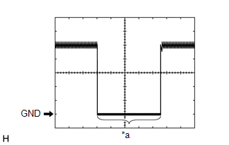
| *a | Kick detection signal |
CHECK CERTIFICATION ECU (SMART KEY ECU ASSEMBLY)
(a) Disconnect the I53 certification ECU (smart key ECU assembly) connector.
.png)
(b) Measure the voltage and resistance according to the value(s) in the table below.
| Terminal No. (Symbol) | Wiring Color | Terminal Description | Condition | Specified Condition |
|---|---|---|---|---|
| I53-10 (+B) - Body ground | W - Body ground | Auxiliary battery power supply | Power switch off | 11 to 14 V |
| I53-11 (E) - Body ground | W-B - Body ground | Body ground | Always | Below 1 Ω |
(c) Reconnect the I53 certification ECU (smart key ECU assembly) connector.
(d) Measure the waveform according to the value(s) in the table below.
| Terminal No. (Symbol) | Wiring Color | Terminal Description | Condition | Specified Condition |
|---|---|---|---|---|
| I52-5 (TSW5) - I53-11 (E) | Y - W-B | Back door opener switch assembly signal | Back door opener switch assembly (open switch) off → on | Pulse generation (See waveform 1) |
(1) Using an oscilloscope, check waveform 1.
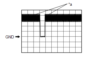
| *a | In actuality, sampling is being performed |
| Item | Content |
|---|---|
| Terminal No. (Symbol) | I52-5 (TSW5) - I53-11 (E) |
| Tool Setting | 2 V/DIV., 500 ms./DIV. |
| Condition | Back door opener switch assembly (open switch) off → on |
CHECK MAIN BODY ECU (MULTIPLEX NETWORK BODY ECU) AND INSTRUMENT PANEL JUNCTION BLOCK ASSEMBLY
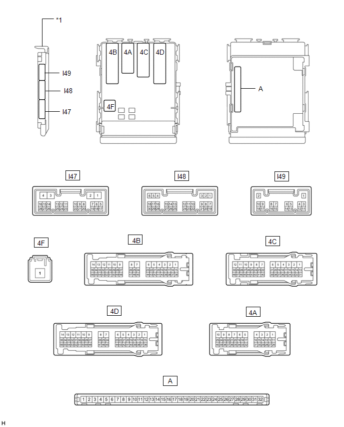
| *1 | Main Body ECU (Multiplex Network Body ECU) | - | - |
(a) Remove the main body ECU (multiplex network body ECU).
Click here .gif)
(b) Connect the instrument panel junction block assembly connectors.
(c) Measure the voltage and resistance according to the value(s) in the table below.
| Terminal No. (Symbol) | Wiring Color | Terminal Description | Condition | Specified Condition |
|---|---|---|---|---|
| A-31 (BECU) - Body ground | None - Body ground | Auxiliary battery power supply | Power switch off | 11 to 14 V |
| A-30 (ACC) - Body ground | None - Body ground | ACC power supply | Power switch on (ACC) | 11 to 14 V |
| Power switch off | Below 1 V | |||
| A-32 (IG) - Body ground | None - Body ground | IG power supply | Power switch on (IG) | 11 to 14 V |
| Power switch off | Below 1 V | |||
| A-11 (GND1) - Body ground | None - Body ground | Body ground | Always | Below 1 Ω |
(d) Install the main body ECU (multiplex network body ECU).
Click here
(e) Measure the voltage and waveform according to the value(s) in the table below.
| Terminal No. (Symbol) | Wiring Color | Terminal Description | Condition | Specified Condition |
|---|---|---|---|---|
| I47-5 (PBDS) - Body ground | R - Body ground | Combination switch assembly signal | Combination switch assembly off | Pulse generation |
| Combination switch assembly on | Below 1 V |
READ NEXT:
 Freeze Frame Data
FREEZE FRAME DATA FREEZE FRAME DATA (a) Whenever a DTC is detected, the multiplex network door ECU stores the current vehicle state as Freeze Frame Data. CHECK FREEZE FRAME DATA (a) Turn the power swi
Data List / Active Test
DATA LIST / ACTIVE TEST DATA LIST HINT: Using the Techstream to read the Data List allows the values or states of switches, sensors, actuators and other items to be read without removing any parts. Th
Diagnostic Trouble Code Chart
DIAGNOSTIC TROUBLE CODE CHART Power Back Door System DTC No. Detection Item Link B2205 Kick Sensor Circuit B2220 Back Door Motor Circuit B2226 PBD Unit Pulse Sensor
SEE MORE:
Relay
On-vehicle InspectionON-VEHICLE INSPECTION PROCEDURE 1. INSPECT HORN RELAY ASSEMBLY (a) Remove the horn relay assembly. (b) Measure the resistance according to the value(s) in the table below. Standard Resistance: Tester Connection Condition Specified Condition 3 - 5 Vo
Installation
INSTALLATION PROCEDURE 1. INSTALL TRANSMISSION CONTROL CABLE ASSEMBLY NOTICE: Before installing the transmission control cable assembly, check that the shift lever position sensor and the shift lever are in neutral. (a) Install the transmission control cable assembly to the body with the 2 bolts.
© 2016-2026 Copyright www.lexunx.com
