Lexus NX: Installation
INSTALLATION
PROCEDURE
1. INSTALL TRANSMISSION CONTROL CABLE ASSEMBLY
NOTICE:
Before installing the transmission control cable assembly, check that the shift lever position sensor and the shift lever are in neutral.
| (a) Install the transmission control cable assembly to the body with the 2 bolts. Torque: 5.0 N·m {51 kgf·cm, 44 in·lbf} |
|
.png)
| (b) Install the transmission control cable assembly to the body with the 2 bolts. Torque: Bolt A : 12 N·m {122 kgf·cm, 9 ft·lbf} Bolt B : 5.0 N·m {51 kgf·cm, 44 in·lbf} |
|
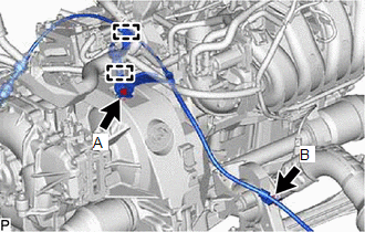
(c) Connect the transmission control cable assembly with the 2 clamps.
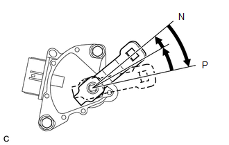
| (d) Turn the control shaft lever clockwise until it stops. Next, turn the control shaft lever counterclockwise 2 notches to set it to N. |
|
| (e) Connect the transmission control cable assembly to the No. 1 transmission control cable bracket, and install a new clip. |
|
.png)
(f) Connect the transmission control cable assembly to the control shaft lever with the nut.
Torque:
12 N·m {122 kgf·cm, 9 ft·lbf}
2. INSTALL INVERTER BRACKET ASSEMBLY
Click here .gif)
3. INSTALL INVERTER WATER PUMP WITH MOTOR ASSEMBLY
Click here
4. INSTALL NO. 1 ENGINE UNDER COVER ASSEMBLY
Click here
5. INSTALL INVERTER WITH CONVERTER ASSEMBLY
Click here
6. CONNECT TRANSMISSION CONTROL CABLE ASSEMBLY
Click here
7. INSTALL REAR CONSOLE BOX ASSEMBLY (w/o ASC System)
Click here
8. INSTALL NO. 1 SPEAKER WITH BOX ASSEMBLY (w/ ASC System)
Click here
READ NEXT:
 Coolant
ReplacementREPLACEMENT PROCEDURE 1. DRAIN ENGINE COOLANT CAUTION: Do not remove the reservoir cap while the engine assembly and radiator assembly are still hot. Pressurized, hot engine coolant and st
SEE MORE:
Installation
INSTALLATION PROCEDURE 1. INSTALL ELECTRICAL KEY ANTENNA NOTICE: Do not reuse dropped or damaged parts. (a) Attach the guide and install the electrical key antenna with the nut. Torque: 7.5 N·m {76 kgf·cm, 66 in·lbf} (b) Connect the connector. 2. INSTALL REAR BUMPER COVER Click here 3. INSTA
Components
COMPONENTS ILLUSTRATION *1 COOLER EXPANSION VALVE *2 NO. 1 COOLER EVAPORATOR SUB-ASSEMBLY *3 NO. 1 COOLER THERMISTOR *4 UPPER HEATER CASE *5 LOWER HEATER CASE *6 O-RING N*m (kgf*cm, ft.*lbf): Specified torque ● Non-reusable part Compressor oil ND-OIL
