Lexus NX: Terminals Of Ecu
TERMINALS OF ECU
CHECK INSTRUMENT PANEL JUNCTION BLOCK ASSEMBLY AND MAIN BODY ECU (MULTIPLEX NETWORK BODY ECU)
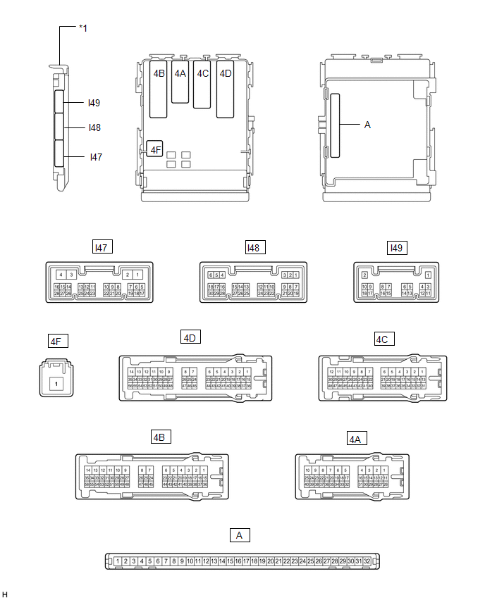
| *1 | Main Body ECU (Multiplex Network Body ECU) | - | - |
(a) Remove the main body ECU (multiplex network body ECU) from the instrument panel junction block assembly.
Click here .gif)
(b) Reconnect the instrument panel junction block assembly connector.
(c) Measure the voltage and resistance according to the value(s) in the table below.
| Tester Connection | Wiring Color | Terminal Description | Condition | Specified Condition |
|---|---|---|---|---|
| A-11 (GND1) - Body ground | - | Ground | Always | Below 1 Ω |
| A-30 (ACC) - Body ground | - | ACC power supply | Power switch on (ACC) | 11 to 14 V |
| Power switch off | Below 1 V | |||
| A-31 (BECU) - Body ground | - | Auxiliary battery power supply | Power switch off | 11 to 14 V |
| A-32 (IG) - Body ground | - | IG power supply | Power switch on (IG) | 11 to 14 V |
| Power switch off | Below 1 V |
(d) Install the main body ECU (multiplex network body ECU) to the instrument panel junction block assembly.
Click here
(e) Measure the voltage and check for pulses according to the value(s) in the table below.
| Tester Connection | Wiring Color | Terminal Description | Condition | Specified Condition |
|---|---|---|---|---|
| I47-2 (LSWR) - Body ground | Y - Body ground | Rear door RH unlock detection switch input | Rear door RH unlocked | Below 1 V |
| Rear door RH locked | Pulse generation | |||
| I48-2 (UL3) - Body ground | LG - Body ground | Driver door key-linked unlock input | Driver door key cylinder turned to neutral position → on (unlock) | Pulse generation → Below 1 V |
| I48-6 (FLCY) - Body ground | G - Body ground | Front door courtesy light switch LH input | Front door LH open | Below 1 V |
| Front door LH closed | Pulse generation | |||
| I48-27 (FRCY) - Body ground | W - Body ground | Front door courtesy light switch RH input | Front door RH open | Below 1 V |
| Front door RH closed | Pulse generation | |||
| I48-29 (L2) - Body ground | R - Body ground | Driver door key-linked lock input | Driver door key cylinder turned to neutral position → on (lock) | Pulse generation → Below 1 V |
| 4A-1 (ACT-) - Body ground | R - Body ground | Door lock motor unlock drive output | Door control switch or driver door key cylinder off → on (unlock) | Below 1 V → 11 to 14 V → Below 1 V |
| 4A-4 (ACT+) - Body ground | R - Body ground | Door lock motor lock drive output | Door control switch or driver door key cylinder off → on (lock) | Below 1 V → 11 to 14 V → Below 1 V |
| 4A-18 (LCTY) - Body ground | W - Body ground | Rear door courtesy light switch LH input | Rear door LH open | Below 1 V |
| Rear door LH closed | Pulse generation | |||
| 4A-21 (BCTY) - Body ground | LG - Body ground*1 R - Body ground*2 | Back door courtesy light switch input | Back door closed | Below 1 V |
| Back door open | Pulse generation | |||
| 4A-25 (TR+) - Body ground*3 | W - Body ground | Back door lock motor drive output | Back door closed → open | Below 1 V → 11 to 14 V → Below 1 V |
| 4A-34 (LSWL) - Body ground | Y - Body ground | Rear door LH unlock detection switch input | Rear door LH unlocked | Below 1 V |
| Rear door LH locked | Pulse generation | |||
| 4D-4 (ACT-) - Body ground | LG - Body ground | Door lock motor unlock drive output | Door control switch or driver door key cylinder off → on (unlock) | Below 1 V → 11 to 14 V → Below 1 V |
| 4C-10 - Body ground | R - Body ground | Door lock power supply | Door control switch or driver door key cylinder off → on (lock or unlock) | 11 to 14 V → Below 1 V → 11 to 14 V |
| 4D-5 (ACT-) - Body ground | B - Body ground | Door lock motor unlock drive output | Door control switch or driver door key cylinder off → on (unlock) | Below 1 V → 11 to 14 V → Below 1 V |
| 4D-10 (ACTD) - Body ground | B - Body ground | Door lock motor unlock drive output | Door control switch or driver door key cylinder off → on (unlock) | Below 1 V → 11 to 14 V → Below 1 V |
| 4D-11 (ACT+) - Body ground | R - Body ground | Door lock motor lock drive output | Door control switch or driver door key cylinder off → on (lock) | Below 1 V → 11 to 14 V → Below 1 V |
| 4D-12 (ACT+) - Body ground | R - Body ground | Door lock motor lock drive output | Door control switch or driver door key cylinder off → on (lock) | Below 1 V → 11 to 14 V → Below 1 V |
| 4D-13 (ACT+) - Body ground | P - Body ground | Door lock motor lock drive output | Door control switch or driver door key cylinder off → on (lock) | Below 1 V → 11 to 14 V → Below 1 V |
| 4D-37 (RCTY) - Body ground | Y - Body ground | Rear door courtesy light switch RH input | Rear door RH open | Below 1 V |
| Rear door RH closed | Pulse generation | |||
| 4D-39 (LSFR) - Body ground | P - Body ground | Front door RH unlock detection switch input | Front door RH unlocked | Below 1 V |
| Front door RH locked | Pulse generation | |||
| 4D-40 (LSFL) - Body ground | B - Body ground | Front door LH unlock detection switch input | Front door LH unlocked | Below 1 V |
| Front door LH locked | Pulse generation | |||
| 4D-42 (L1) - Body ground | V - Body ground | Door control switch assembly input | Door control switch assembly off → on (lock) | Pulse generation → Below 1 V |
| 4D-46 (GSW) - Body ground | B - Body ground | Unlock detection input | Power switch on (IG) | 2.8 to 4.3 V |
| 4D-55 (UL1) - Body ground | W - Body ground | Door control switch assembly input | Door control switch assembly off → on (unlock) | Pulse generation → Below 1 V |
- *1: w/ Rear Power Seat System
- *2: w/o Rear Power Seat System
- *3: w/o Power Back Door System
CHECK CERTIFICATION ECU
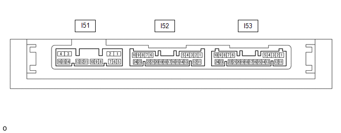
(a) Disconnect the I53 certification ECU (smart key ECU assembly) connector.
(b) Measure the voltage and resistance according to the value(s) in the table below.
| Tester Connection | Wiring Color | Terminal Description | Condition | Specified Condition |
|---|---|---|---|---|
| I53-10 (+B) - Body ground | W - Body ground | Auxiliary battery power supply | Power switch off | 11 to 14 V |
| I53-11 (E) - Body ground | W-B - Body ground | Ground | Always | Below 1 Ω |
(c) Reconnect the I53 certification ECU (smart key ECU assembly) connector.
(d) Check for pulses according to the value(s) in the table below.
| Tester Connection | Wiring Color | Terminal Description | Condition | Specified Condition |
|---|---|---|---|---|
| I52-5 (TSW5) - Body ground | Y - Body ground | Back door opener switch input | Back door opener switch assembly (open switch) off → on | Pulse generation |
| I52-13 (TSW6) - Body ground | L - Body ground | Back door opener switch input | Back door opener switch assembly (lock switch) off → on | Pulse generation |
CHECK AIRBAG ECU ASSEMBLY
Click here
READ NEXT:
 Diagnosis System
DIAGNOSIS SYSTEM CHECK DLC3 (a) Check the DLC3. Click here INSPECT AUXILIARY BATTERY VOLTAGE (a) Measure the auxiliary battery voltage. Standard voltage: 11 to 14 V (power switch off) If the voltag
Dtc Check / Clear
DTC CHECK / CLEAR CHECK DTC (a) Connect the Techstream to the DLC3. (b) Turn the power switch on (IG). (c) Turn the Techstream on. (d) Enter the following menus: Body Electrical / Main Body / Trouble
Data List / Active Test
DATA LIST / ACTIVE TEST DATA LIST HINT: Using the Techstream to read the Data List allows the values or states of switches, sensors, actuators and other items to be read without removing any parts. Th
SEE MORE:
Switch Lights of Remote Touch do not Illuminate
DESCRIPTION Power is supplied to the remote touch illumination when the light control switch is in the tail or head position. WIRING DIAGRAM CAUTION / NOTICE / HINT NOTICE: Inspect the fuse for circuits related to this system before performing the following procedure. PROCEDURE 1. CONFIRM SYM
Terminals Of Ecu
TERMINALS OF ECU HINT: Perform the inspection from the harness side with the connectors connected. STEERING HEATER AND VIBRATION ECU (a) Measure the voltage or resistance according to the value(s) in the table below. Terminal No. (Symbol) Terminal Description Condition Specified Condition
