- Power switch off
- Electrical key transmitter sub-assembly brought outside detection area but kept inside wireless function operational area
- Lock or unlock switch of electrical key transmitter sub-assembly not pressed → pressed
Lexus NX: Terminals Of Ecu
Lexus NX Service Manual / Vehicle Interior / Door Lock / Wireless Door Lock Control System / Terminals Of Ecu
TERMINALS OF ECU
CHECK INSTRUMENT PANEL JUNCTION BLOCK ASSEMBLY AND MAIN BODY ECU (MULTIPLEX NETWORK BODY ECU)
.png)
| *1 | Main Body ECU (Multiplex Network Body ECU) | - | - |
(a) Remove the main body ECU (multiplex network body ECU) from the instrument panel junction block assembly.
Click here .gif)
(b) Reconnect the instrument panel junction block assembly connector.
(c) Measure the voltage and resistance according to the value(s) in the table below.
| Tester Connection | Wiring Color | Terminal Description | Condition | Specified Condition |
|---|---|---|---|---|
| A-11 (GND1) - Body ground | - | Ground | Always | Below 1 Ω |
| A-30 (ACC) - Body ground | - | ACC power supply | Power switch on (ACC) | 11 to 14 V |
| Power switch off | Below 1 V | |||
| A-31 (BECU) - Body ground | - | Auxiliary battery power supply | Power switch off | 11 to 14 V |
| A-32 (IG) - Body ground | - | IG power supply | Power switch on (IG) | 11 to 14 V |
| Power switch off | Below 1 V |
(d) Install the main body ECU (multiplex network body ECU) to the instrument panel junction block assembly.
Click here
(e) Measure the voltage and check for pulses according to the value(s) in the table below.
| Tester Connection | Wiring Color | Terminal Description | Condition | Specified Condition |
|---|---|---|---|---|
| I47-2 (LSWR) - Body ground | Y - Body ground | Rear door RH unlock detection switch input | Rear door RH unlocked | Below 1 V |
| Rear door RH locked | Pulse generation | |||
| I48-2 (UL3) - Body ground | LG - Body ground | Driver door key-linked unlock input | Driver door key cylinder turned to neutral position → on (unlock) | Pulse generation → Below 1 V |
| I48-6 (FLCY) - Body ground | G - Body ground | Front door courtesy light switch LH input | Front door LH open | Below 1 V |
| Front door LH closed | Pulse generation | |||
| I48-27 (FRCY) - Body ground | W - Body ground | Front door courtesy light switch RH input | Front door RH open | Below 1 V |
| Front door RH closed | Pulse generation | |||
| I48-29 (L2) - Body ground | R - Body ground | Driver door key-linked lock input | Driver door key cylinder turned to neutral position → on (lock) | Pulse generation → Below 1 V |
| 4A-1 (ACT-) - Body ground | R - Body ground | Door lock motor unlock drive output | Door control switch or driver door key cylinder off → on (unlock) | Below 1 V → 11 to 14 V → Below 1 V |
| 4A-4 (ACT+) - Body ground | R - Body ground | Door lock motor lock drive output | Door control switch or driver door key cylinder off → on (lock) | Below 1 V → 11 to 14 V → Below 1 V |
| 4A-18 (LCTY) - Body ground | W - Body ground | Rear door courtesy light switch LH input | Rear door LH open | Below 1 V |
| Rear door LH closed | Pulse generation | |||
| 4A-21 (BCTY) - Body ground | LG - Body ground*1 R - Body ground*2 | Back door courtesy light switch input | Back door open | Below 1 V |
| Back door closed | Pulse generation | |||
| 4A-25 (TR+) - Body ground*3 | W - Body ground | Back door lock motor drive output | Back door closed → open | Below 1 V → 11 to 14 V → Below 1 V |
| 4A-34 (LSWL) - Body ground | Y - Body ground | Rear door LH unlock detection switch input | Rear door LH unlocked | Below 1 V |
| Rear door LH locked | Pulse generation | |||
| 4B-52 (BZR) - Body ground | P - Body ground | Wireless door lock buzzer output | Power switch off, all doors closed, electrical key transmitter sub-assembly no inside vehicle and lock or unlock switch of electrical key transmitter sub-assembly not pressed → pressed (wireless door lock buzzer answer-back) | Below 1 V → Pulse generation |
| 4D-4 (ACT-) - Body ground | LG - Body ground | Door lock motor unlock drive output | Door control switch or driver door key cylinder off → on (unlock) | Below 1 V → 11 to 14 V → Below 1 V |
| 4C-10 - Body ground | R - Body ground | Door lock power supply | Door control switch or driver door key cylinder off → on (lock or unlock) | 11 to 14 V → Below 1 V → 11 to 14 V |
| 4D-5 (ACT-) - Body ground | B - Body ground | Door lock motor unlock drive output | Door control switch or driver door key cylinder off → on (unlock) | Below 1 V → 11 to 14 V → Below 1 V |
| 4D-10 (ACTD) - Body ground | B - Body ground | Door lock motor unlock drive output | Door control switch or driver door key cylinder off → on (unlock) | Below 1 V → 11 to 14 V → Below 1 V |
| 4D-11 (ACT+) - Body ground | R - Body ground | Door lock motor lock drive output | Door control switch or driver door key cylinder off → on (lock) | Below 1 V → 11 to 14 V → Below 1 V |
| 4D-12 (ACT+) - Body ground | R - Body ground | Door lock motor lock drive output | Door control switch or driver door key cylinder off → on (lock) | Below 1 V → 11 to 14 V → Below 1 V |
| 4D-13 (ACT+) - Body ground | P - Body ground | Door lock motor lock drive output | Door control switch or driver door key cylinder off → on (lock) | Below 1 V → 11 to 14 V → Below 1 V |
| 4D-37 (RCTY) - Body ground | Y - Body ground | Rear door courtesy light switch RH input | Rear door RH open | Below 1 V |
| Rear door RH closed | Pulse generation | |||
| 4D-39 (LSFR) - Body ground | P - Body ground | Front door RH unlock detection switch input | Front door RH unlocked | Below 1 V |
| Front door RH locked | Pulse generation | |||
| 4D-40 (LSFL) - Body ground | B - Body ground | Front door LH unlock detection switch input | Front door LH unlocked | Below 1 V |
| Front door LH locked | Pulse generation |
- *1: w/ Rear Power Seat System
- *2: w/o Rear Power Seat System
- *3: w/o Power Back Door System
CHECK CERTIFICATION ECU (SMART KEY ECU ASSEMBLY)
.png)
(a) Disconnect the I53 certification ECU (smart key ECU assembly) connector.
(b) Measure the voltage and resistance according to the value(s) in the table below.
| Tester Connection | Wiring Color | Terminal Description | Condition | Specified Condition |
|---|---|---|---|---|
| I53-10 (+B) - Body ground | W - Body ground | Auxiliary battery power supply | Power switch off | 11 to 14 V |
| I53-11 (E) - Body ground | W-B - Body ground | Ground | Always | Below 1 Ω |
(c) Reconnect the I53 certification ECU (smart key ECU assembly) connector.
(d) Measure the voltage and check for pulses according to the value(s) in the table below.
| Tester Connection | Wiring Color | Terminal Description | Condition | Specified Condition |
|---|---|---|---|---|
| I52-18 (RCO) - I53-11 (E) | R - W-B | Output to door control receiver (Power supply for door control receiver. Certification ECU [smart key ECU assembly] outputs 5 V when receiver starts operating.) | Proceed: | Pulse generation (See waveform 1) |
| I52-19 (CSEL) - I53-11 (E) | B - W-B | Communication channel switching circuit | Proceed:
| Below 1 V → Pulse generation |
| I52-20 (RDAM) - I53-11 (E) | L - W-B | Door control receiver verifies data received from electrical key transmitter sub-assembly. Door control receiver sends data from electrical key transmitter sub-assembly to certification ECU (smart key ECU assembly) (Door control receiver intermittently grounds 12 V signal from certification ECU [smart key ECU assembly]). | Proceed:
| Pulse generation (See waveform 2) |
(e) Using an oscilloscope, check waveform 1.
HINT:
The oscilloscope waveform shown in the illustration is an example for reference only. Noise, chattering, etc. are not shown.
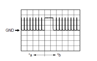
| *a | Before lock or unlock switch of electrical key transmitter sub-assembly pressed |
| *b | After lock or unlock switch of electrical key transmitter sub-assembly pressed |
| Item | Content |
|---|---|
| Tester Connection | I52-18 (RCO) - I53-11 (E) |
| Tool Setting | 2 V/DIV., 500 ms/DIV. |
| Condition | Procedure:
|
(f) Using an oscilloscope, check waveform 2.
HINT:
The oscilloscope waveform shown in the illustration is an example for reference only. Noise, chattering, etc. are not shown.
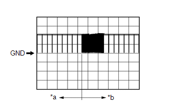
| *a | Before lock or unlock switch of electrical key transmitter sub-assembly pressed |
| *b | After lock or unlock switch of electrical key transmitter sub-assembly pressed |
| Item | Content |
|---|---|
| Tester Connection | I52-20 (RDAM) - I53-11 (E) |
| Tool Setting | 5 V/DIV., 500 ms/DIV. |
| Condition | Procedure:
|
READ NEXT:
 Diagnosis System
DIAGNOSIS SYSTEM DESCRIPTION The ECU stores DTCs when malfunctions occur. The diagnostic system allows for reading of the DTCs from the DLC3. Use the Techstream to check for malfunctions and perform r
Dtc Check / Clear
DTC CHECK / CLEAR CHECK DTC (a) Connect the Techstream to the DLC3. (b) Turn the power switch on (IG). (c) Turn the Techstream on. (d) Enter the following menus: Body Electrical / Smart Access / Troub
Data List / Active Test
DATA LIST / ACTIVE TEST DATA LIST HINT: Using the Techstream to read the Data List allows the values or states of switches, sensors, actuators and other items to be read without removing any parts. Th
SEE MORE:
Front Recognition Camera Heater Malfunction (C1AAE00)
DESCRIPTION The forward recognition camera controls the current to the forward recognition hood with heater sub-assembly. C1AAE00 is stored when the forward recognition camera detects a forward recognition hood with heater sub-assembly operation circuit malfunction. DTC No. Detection Item DTC
Speaker Circuit
DESCRIPTION If there is a short in a speaker circuit, the stereo component amplifier assembly detects it and stops output to the speakers. As a result, sound cannot be heard from the speakers even if there is no malfunction in the stereo component amplifier assembly, DCM (telematics transceiver)* or
© 2016-2026 Copyright www.lexunx.com
